Information injection-pump assembly
BOSCH
F 019 Z20 018
f019z20018
ZEXEL
101608-6292
1016086292
MITSUBISHI
ME440070
me440070
Rating:
Service parts 101608-6292 INJECTION-PUMP ASSEMBLY:
1.
_

6.
COUPLING PLATE
7.
COUPLING PLATE
8.
_
9.
_

11.
Nozzle and Holder
12.
Open Pre:MPa(Kqf/cm2)
17.7(180)
15.
NOZZLE SET
Include in #1:
101608-6292
as INJECTION-PUMP ASSEMBLY
Include in #2:
104748-0482
as _
Cross reference number
BOSCH
F 019 Z20 018
f019z20018
ZEXEL
101608-6292
1016086292
MITSUBISHI
ME440070
me440070
Zexel num
Bosch num
Firm num
Name
101608-6292
F 019 Z20 018
ME440070 MITSUBISHI
INJECTION-PUMP ASSEMBLY
6D16TL K 14BN INJECTION PUMP ASSY PE
6D16TL K 14BN INJECTION PUMP ASSY PE
Calibration Data:
Adjustment conditions
Test oil
1404 Test oil ISO4113 or {SAEJ967d}
1404 Test oil ISO4113 or {SAEJ967d}
Test oil temperature
degC
40
40
45
Nozzle and nozzle holder
105780-8140
Bosch type code
EF8511/9A
Nozzle
105780-0000
Bosch type code
DN12SD12T
Nozzle holder
105780-2080
Bosch type code
EF8511/9
Opening pressure
MPa
17.2
Opening pressure
kgf/cm2
175
Injection pipe
Outer diameter - inner diameter - length (mm) mm 6-2-600
Outer diameter - inner diameter - length (mm) mm 6-2-600
Overflow valve
131424-5520
Overflow valve opening pressure
kPa
255
221
289
Overflow valve opening pressure
kgf/cm2
2.6
2.25
2.95
Tester oil delivery pressure
kPa
255
255
255
Tester oil delivery pressure
kgf/cm2
2.6
2.6
2.6
Direction of rotation (viewed from drive side)
Left L
Left L
Injection timing adjustment
Direction of rotation (viewed from drive side)
Left L
Left L
Injection order
1-5-3-6-
2-4
Pre-stroke
mm
4.5
4.45
4.55
Beginning of injection position
Governor side NO.1
Governor side NO.1
Difference between angles 1
Cal 1-5 deg. 60 59.5 60.5
Cal 1-5 deg. 60 59.5 60.5
Difference between angles 2
Cal 1-3 deg. 120 119.5 120.5
Cal 1-3 deg. 120 119.5 120.5
Difference between angles 3
Cal 1-6 deg. 180 179.5 180.5
Cal 1-6 deg. 180 179.5 180.5
Difference between angles 4
Cyl.1-2 deg. 240 239.5 240.5
Cyl.1-2 deg. 240 239.5 240.5
Difference between angles 5
Cal 1-4 deg. 300 299.5 300.5
Cal 1-4 deg. 300 299.5 300.5
Injection quantity adjustment
Adjusting point
A
Rack position
11.5
Pump speed
r/min
1400
1400
1400
Average injection quantity
mm3/st.
116
115
117
Max. variation between cylinders
%
0
-2.5
2.5
Basic
*
Fixing the lever
*
Boost pressure
kPa
54.7
54.7
Boost pressure
mmHg
410
410
Injection quantity adjustment_02
Adjusting point
C
Rack position
8.1+-0.5
Pump speed
r/min
325
325
325
Average injection quantity
mm3/st.
8.5
7
10
Max. variation between cylinders
%
0
-15
15
Fixing the rack
*
Boost pressure
kPa
0
0
0
Boost pressure
mmHg
0
0
0
Injection quantity adjustment_03
Adjusting point
E
Rack position
11.7++
Pump speed
r/min
100
100
100
Average injection quantity
mm3/st.
95
95
105
Fixing the lever
*
Boost pressure
kPa
0
0
0
Boost pressure
mmHg
0
0
0
Rack limit
*
Boost compensator adjustment
Pump speed
r/min
650
650
650
Rack position
9.5
Boost pressure
kPa
15.3
8.6
22
Boost pressure
mmHg
115
65
165
Boost compensator adjustment_02
Pump speed
r/min
650
650
650
Rack position
10.7
Boost pressure
kPa
45.3
42.6
48
Boost pressure
mmHg
340
320
360
Timer adjustment
Pump speed
r/min
1070--
Advance angle
deg.
0
0
0
Load
4/4
Remarks
Beginning of advance.
Beginning of advance.
Timer adjustment_02
Pump speed
r/min
440
Advance angle
deg.
3
2.5
3.5
Load
0/4
Remarks
Start
Start
Timer adjustment_03
Pump speed
r/min
-
Advance angle
deg.
0
0
0
Load
0/4
Remarks
Measure the actual speed.
Measure the actual speed.
Timer adjustment_04
Pump speed
r/min
1020
Advance angle
deg.
0.5
Load
4/4
Timer adjustment_05
Pump speed
r/min
1330
Advance angle
deg.
3
2.5
3.5
Load
4/4
Remarks
Finish
Finish
Test data Ex:
Governor adjustment
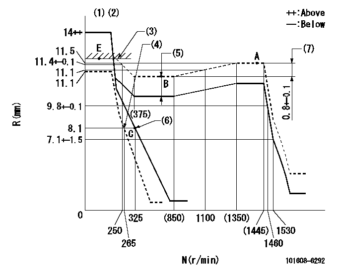
N:Pump speed
R:Rack position (mm)
(1)Notch fixed: K
(2)Tolerance for racks not indicated: +-0.05mm.
(3)RACK LIMIT
(4)Set idle sub-spring
(5)Boost compensator stroke: BCL
(6)Main spring setting
(7)Rack difference between N = N1 and N = N2
----------
K=11 BCL=1.2+-0.1mm N1=1400r/min N2=650r/min
----------
----------
K=11 BCL=1.2+-0.1mm N1=1400r/min N2=650r/min
----------
Speed control lever angle
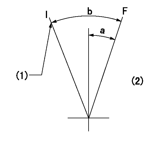
F:Full speed
I:Idle
(1)Stopper bolt setting
(2)Base lever only
----------
----------
a=(17deg)+-5deg b=(34deg)+-5deg
----------
----------
a=(17deg)+-5deg b=(34deg)+-5deg
Stop lever angle
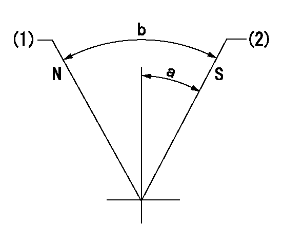
N:Pump normal
S:Stop the pump.
(1)Normal
(2)Pump speed aa and rack position bb (to be sealed at delivery)
----------
aa=0r/min bb=4-0.5mm
----------
a=28deg+-5deg b=(48deg)
----------
aa=0r/min bb=4-0.5mm
----------
a=28deg+-5deg b=(48deg)
0000001501 TAMPER PROOF

Tamperproofing-equipped boost compensator cover installation procedure
(A) After adjusting the boost compensator, tighten the bolts to remove the heads.
(1)Before adjusting the governor and the boost compensator, tighten the screw to the specified torque.
(Tightening torque T = T1 maximum)
(2)After adjusting the governor and the boost compensator, tighten to the specified torque to break off the bolt heads.
(Tightening torque T = T2)
----------
T1=2.5N-m(0.25kgf-m) T2=2.9~4.4N-m(0.3~0.45kgf-m)
----------
----------
T1=2.5N-m(0.25kgf-m) T2=2.9~4.4N-m(0.3~0.45kgf-m)
----------
Timing setting

(1)Pump vertical direction
(2)Coupling's key groove position at No 1 cylinder's beginning of injection
(3)B.T.D.C.: aa
(4)-
----------
aa=6.5deg
----------
a=(3deg)
----------
aa=6.5deg
----------
a=(3deg)
Information:
AFFECTED PRODUCT
Model Identification Number
D6R III GMT00101-00170
HCD00123-00155
TBC00100-00191
D6R III LGP DMK00130-00208
JWD00250
LGP00164-00166
WRG00158-00564
D6R III XL GJB00173-00622
JDL00113-00202
LAE00125
LFM00111-00180
D6R III XW DPS00120-00132
MRT00163-00387
D6R IIIP LGP DLM00161-00162
WCB00112-00184
D6R IIIP XL HKE00146-00221
RFC00140
D6R IIIP XW DJG00250-00251
HDC00133-00211
MTJ00151-00152
PARTS NEEDED
No parts needed for this program
ACTION REQUIRED
Please refer to the attached Rework Procedure.
OWNER NOTIFICATION
U.S. and Canadian owners will receive the attached Owner Notification.
SERVICE CLAIM ALLOWANCES
Caterpillar Dealer Suggested Customer Suggested
Parts % Labor Hrs% Parts % Labor Hrs% Parts % Labor Hrs%
100% 100% 0% 0% 0% 0%
This is a 1.0-hour job
PARTS DISPOSITION
Handle the parts in accordance with your Warranty Bulletin on warranty parts handling.
MAKE EVERY EFFORT TO COMPLETE THIS PROGRAM AS SOON AS POSSIBLE.
COPY OF OWNER NOTIFICATION FOR U.S. AND CANADIAN OWNERS
XYZ Corporation
3240 Arrow Drive
Anywhere, YZ 99999
PRIORITY - PRODUCT IMPROVEMENT PROGRAM FOR FLASHING INJECTOR ETRIM FILES
MODELS INVOLVED - CERTAIN D6R III, D6R IIIP XW, D6R IIIP LGP, D6R III LGP, D6R III XW, AND D6R III XL TRACK TYPE TRACTORS
Dear Caterpillar Product Owner:
New injector etrim files need to be installed on the products listed below. The upgraded files will help performance and stability of your D6R engine. You will not be charged for the service performed.
Contact your local Caterpillar dealer immediately to schedule this service. The dealer will advise you of the time required to complete this service.
Please refer the dealer to their Service Letter dated 31Aug2006 when scheduling this service.
We regret the inconvenience this may cause you, but urge you to have this service performed as soon as possible to prevent unscheduled downtime.
Caterpillar Inc.
Identification #(s)
Attached to 31Aug2006 Service Letter
Rework Procedure
Field Rework Procedure
1. Using the provided machine serial number of the D6R Series III tractor in your service area, go to TMI web and look up the engine serial number.
2. Look up your engine serial number on the Excell file emailed to all machine TCs in order to access the injector serial numbers. If you don't have a copy of this file go the the Knowledge Network to get the file from the following web address: https://kn.cat.com/message.cfm?id=4388&parent=153301&type=Broadcast
3. Copy the 6 injector serial numbers for each machine in your service area and go to SIS web.
4. At the main menu click on Service Software Files.
5. Follow the directions and down load the trim file for each injector, putting them on a disk or in a file that can be accessed from ET.
6. Down load the six trim files for the injectors and program into the ECM in the correct order, using ET.
7. Make sure the machine SN and /or engine SN are included in the service letter claim
Have questions with 101608-6292?
Group cross 101608-6292 ZEXEL
Mitsubishi
Mitsubishi
Mitsubishi
Mitsubishi
Mitsubishi
Mitsubishi
Mitsubishi
Mitsubishi
Mitsubishi
Mitsubishi
101608-6292
F 019 Z20 018
ME440070
INJECTION-PUMP ASSEMBLY
6D16TL
6D16TL