Information injection-pump assembly
ZEXEL
101608-6141
1016086141

Rating:
Cross reference number
ZEXEL
101608-6141
1016086141
Zexel num
Bosch num
Firm num
Name
101608-6141
INJECTION-PUMP ASSEMBLY
Calibration Data:
Adjustment conditions
Test oil
1404 Test oil ISO4113 or {SAEJ967d}
1404 Test oil ISO4113 or {SAEJ967d}
Test oil temperature
degC
40
40
45
Nozzle and nozzle holder
105780-8140
Bosch type code
EF8511/9A
Nozzle
105780-0000
Bosch type code
DN12SD12T
Nozzle holder
105780-2080
Bosch type code
EF8511/9
Opening pressure
MPa
17.2
Opening pressure
kgf/cm2
175
Injection pipe
Outer diameter - inner diameter - length (mm) mm 6-2-600
Outer diameter - inner diameter - length (mm) mm 6-2-600
Overflow valve
131424-5520
Overflow valve opening pressure
kPa
255
221
289
Overflow valve opening pressure
kgf/cm2
2.6
2.25
2.95
Tester oil delivery pressure
kPa
157
157
157
Tester oil delivery pressure
kgf/cm2
1.6
1.6
1.6
Direction of rotation (viewed from drive side)
Left L
Left L
Injection timing adjustment
Direction of rotation (viewed from drive side)
Left L
Left L
Injection order
1-5-3-6-
2-4
Pre-stroke
mm
4.5
4.45
4.55
Beginning of injection position
Governor side NO.1
Governor side NO.1
Difference between angles 1
Cal 1-5 deg. 60 59.5 60.5
Cal 1-5 deg. 60 59.5 60.5
Difference between angles 2
Cal 1-3 deg. 120 119.5 120.5
Cal 1-3 deg. 120 119.5 120.5
Difference between angles 3
Cal 1-6 deg. 180 179.5 180.5
Cal 1-6 deg. 180 179.5 180.5
Difference between angles 4
Cyl.1-2 deg. 240 239.5 240.5
Cyl.1-2 deg. 240 239.5 240.5
Difference between angles 5
Cal 1-4 deg. 300 299.5 300.5
Cal 1-4 deg. 300 299.5 300.5
Injection quantity adjustment
Adjusting point
A
Rack position
10.6
Pump speed
r/min
1050
1050
1050
Average injection quantity
mm3/st.
108
107
109
Max. variation between cylinders
%
0
-2.5
2.5
Basic
*
Fixing the lever
*
Boost pressure
kPa
50.7
50.7
Boost pressure
mmHg
380
380
Injection quantity adjustment_02
Adjusting point
C
Rack position
7.6+-0.5
Pump speed
r/min
425
425
425
Average injection quantity
mm3/st.
9.5
8
11
Max. variation between cylinders
%
0
-15
15
Fixing the rack
*
Boost pressure
kPa
0
0
0
Boost pressure
mmHg
0
0
0
Injection quantity adjustment_03
Adjusting point
E
Rack position
-
Pump speed
r/min
100
100
100
Average injection quantity
mm3/st.
120
110
130
Fixing the lever
*
Boost pressure
kPa
0
0
0
Boost pressure
mmHg
0
0
0
Rack limit
*
Boost compensator adjustment
Pump speed
r/min
700
700
700
Rack position
R1-0.7
Boost pressure
kPa
22.7
20
25.4
Boost pressure
mmHg
170
150
190
Boost compensator adjustment_02
Pump speed
r/min
700
700
700
Rack position
R1(10.6)
Boost pressure
kPa
37.3
30.6
44
Boost pressure
mmHg
280
230
330
Timer adjustment
Pump speed
r/min
1100++
Advance angle
deg.
0
0
0
Remarks
Do not advance until starting N = 1100.
Do not advance until starting N = 1100.
Timer adjustment_02
Pump speed
r/min
-
Advance angle
deg.
4
4
4
Remarks
Measure the actual speed, stop
Measure the actual speed, stop
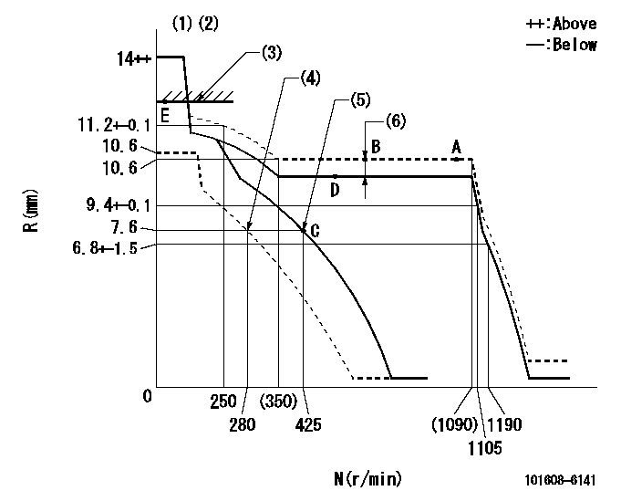
Test data Ex:
Governor adjustment

N:Pump speed
R:Rack position (mm)
(1)Notch fixed: K
(2)Tolerance for racks not indicated: +-0.05mm.
(3)RACK LIMIT
(4)Set idle sub-spring
(5)Main spring setting
(6)Boost compensator stroke: BCL
----------
K=10 BCL=0.7+-0.1mm
----------
----------
K=10 BCL=0.7+-0.1mm
----------
Speed control lever angle

F:Full speed
I:Idle
(1)Stopper bolt setting
----------
----------
a=(20deg)+-5deg b=(5deg)+-5deg
----------
----------
a=(20deg)+-5deg b=(5deg)+-5deg
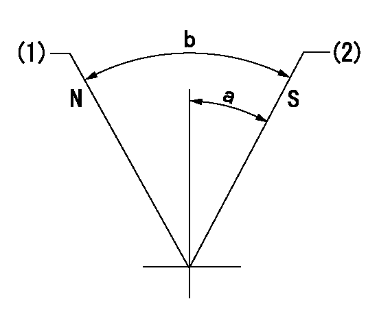
Stop lever angle

N:Pump normal
S:Stop the pump.
(1)Normal
(2)Pump speed aa and rack position bb (to be sealed at delivery)
----------
aa=0r/min bb=1-0.5mm
----------
a=35deg+-5deg b=(55deg)
----------
aa=0r/min bb=1-0.5mm
----------
a=35deg+-5deg b=(55deg)
Timing setting

(1)Pump vertical direction
(2)Coupling's key groove position at No 1 cylinder's beginning of injection
(3)B.T.D.C.: aa
(4)-
----------
aa=14deg
----------
a=(7deg)
----------
aa=14deg
----------
a=(7deg)
Information:
This is a 1.5-hour job for Group 2
1) An additional allowance of 4.0 hours can be claimed if the pump needs to be replaced after failing inspection.
2) Should the Dealer not have access to a Bore Scope an allowance of $250 per Dealer is allowed for the purchase of this tool.
PARTS DISPOSITION
Handle the parts in accordance with your Warranty Bulletin on warranty parts handling.
For NACD
Caterpillar Inc.
Attn: Supplier Recovery
Service Claims Room
8201 N. University
Peoria, IL 61615
MAKE EVERY EFFORT TO COMPLETE THIS PROGRAM AS SOON AS POSSIBLE.
COPY OF OWNER NOTIFICATION FOR U.S. AND CANADIAN OWNERS
XYZ Corporation
3240 Arrow Drive
Anywhere, YZ 99999
SAFETY - PRODUCT IMPROVEMENT PROGRAM FOR THE INSPECTION AND POSSIBLE REPLACEMENT OF THE FUEL INJECTION PUMP ON CERTAIN TURBOCHARGED 414E, 416E, 420E, AND 430E BACKHOE LOADERS
MODELS INVOLVED - 414E, 416E, 420E, 430E
Dear Caterpillar Product Owner:
The Fuel Injection Pump needs to be inspected and possibly replaced on the products listed below. The existing Fuel Injection Pump can cause an unexpected increase in engine speed which may result in personal injury or death.
You will not be charged for the service performed.
Contact your local Caterpillar dealer immediately to schedule this service. The dealer will advise you of the time required to complete this service.
Please refer the dealer to their Service Letter dated 08May2008 when scheduling this service.
We regret the inconvenience this may cause you, but urge you to have this service performed for your added safety and satisfaction.
Caterpillar Inc.
Identification #(s)
Attached to 08May2008 Service Letter
Rework Procedure
Tools required for the inspection of the fuel injection pump are:
17 mm hexagonal socket 3/8" drive.
3/8" drive ratchet wrench with 300 mm extension
Bore Scope with flexible end and ninety degree viewing lens. The Bore Scope has to be capable of being inserted in a 10 mm diameter hole. A 6 mm Bore Scope is recommended for optimium viewing.
1) Before proceeding, first check the serial number shown on the pump identification plate. Image 1.1.1
Image1.1.1
If the machine is identified in the Affected Product and the fuel pump serial number ends with the letter "B" as indicated in image 1.1.1 then the fuel pump should be further inspected.
2) Remove engine compartment door by removing the three bolts holding the door in place using a 13 mm ratchet and socket. Pull the rear of the door away from the machine and then pull the door towards the rear of the machine to remove it from the radiator guard. Image 1.2.1
Image1.2.1
3) Record pump and engine serial number.
Only carry out the following procedure if the pump type number is identified with the "B". (The pumps without the "B" are not affected by this problem).
4) Ensure the area around the fuel return connection is clean. The connection is on the top of the fuel pump toward the front of the engine. Image 1.3.1
Image1.3.1
5) Use a 17 mm X 3/8" drive hexagonal socket, extension 3/8" x 3/8" x 300 mm length and ratchet wrench 3/8" drive to release and remove the return connection fitting.
Note: Be careful not to damage the fitting and o-rings (image 1.4.1), and ensure nothing is
Have questions with 101608-6141?
Group cross 101608-6141 ZEXEL
Mitsubishi
Mitsubishi
Mitsubishi
101608-6141
INJECTION-PUMP ASSEMBLY