Information injection-pump assembly
BOSCH
9 400 611 519
9400611519
ZEXEL
101608-1940
1016081940
MITSUBISHI
ME170446
me170446
Rating:
Service parts 101608-1940 INJECTION-PUMP ASSEMBLY:
1.
_
6.
COUPLING PLATE
7.
COUPLING PLATE
8.
_
9.
_
11.
Nozzle and Holder
ME075788
12.
Open Pre:MPa(Kqf/cm2)
15.7{160}/21.6{220}
14.
NOZZLE
Cross reference number
BOSCH
9 400 611 519
9400611519
ZEXEL
101608-1940
1016081940
MITSUBISHI
ME170446
me170446
Zexel num
Bosch num
Firm num
Name
101608-1940
9 400 611 519
ME170446 MITSUBISHI
INJECTION-PUMP ASSEMBLY
6D16 K 14BF INJECTION PUMP ASSY PE6AD PE
6D16 K 14BF INJECTION PUMP ASSY PE6AD PE
Calibration Data:
Adjustment conditions
Test oil
1404 Test oil ISO4113 or {SAEJ967d}
1404 Test oil ISO4113 or {SAEJ967d}
Test oil temperature
degC
40
40
45
Nozzle and nozzle holder
105780-8260
Bosch type code
9 430 610 133
Nozzle
105780-0120
Bosch type code
1 688 901 990
Nozzle holder
105780-2190
Opening pressure
MPa
18
Opening pressure
kgf/cm2
184
Injection pipe
Outer diameter - inner diameter - length (mm) mm 6-2-600
Outer diameter - inner diameter - length (mm) mm 6-2-600
Overflow valve
131424-8420
Overflow valve opening pressure
kPa
255
221
289
Overflow valve opening pressure
kgf/cm2
2.6
2.25
2.95
Tester oil delivery pressure
kPa
255
255
255
Tester oil delivery pressure
kgf/cm2
2.6
2.6
2.6
Direction of rotation (viewed from drive side)
Left L
Left L
Injection timing adjustment
Direction of rotation (viewed from drive side)
Left L
Left L
Injection order
1-5-3-6-
2-4
Pre-stroke
mm
3.2
3.15
3.25
Beginning of injection position
Governor side NO.1
Governor side NO.1
Difference between angles 1
Cal 1-5 deg. 60 59.5 60.5
Cal 1-5 deg. 60 59.5 60.5
Difference between angles 2
Cal 1-3 deg. 120 119.5 120.5
Cal 1-3 deg. 120 119.5 120.5
Difference between angles 3
Cal 1-6 deg. 180 179.5 180.5
Cal 1-6 deg. 180 179.5 180.5
Difference between angles 4
Cyl.1-2 deg. 240 239.5 240.5
Cyl.1-2 deg. 240 239.5 240.5
Difference between angles 5
Cal 1-4 deg. 300 299.5 300.5
Cal 1-4 deg. 300 299.5 300.5
Injection quantity adjustment
Adjusting point
-
Rack position
11.4
Pump speed
r/min
850
850
850
Each cylinder's injection qty
mm3/st.
84.5
82
87
Basic
*
Fixing the rack
*
Standard for adjustment of the maximum variation between cylinders
*
Injection quantity adjustment_02
Adjusting point
Z
Rack position
9.5+-0.5
Pump speed
r/min
310
310
310
Each cylinder's injection qty
mm3/st.
10.8
9.2
12.4
Fixing the rack
*
Standard for adjustment of the maximum variation between cylinders
*
Injection quantity adjustment_03
Adjusting point
A
Rack position
R1(11.4)
Pump speed
r/min
850
850
850
Average injection quantity
mm3/st.
84.5
83.5
85.5
Basic
*
Fixing the lever
*
Injection quantity adjustment_04
Adjusting point
B
Rack position
R1+0.4
Pump speed
r/min
1450
1450
1450
Average injection quantity
mm3/st.
85.5
81.5
89.5
Fixing the lever
*
Injection quantity adjustment_05
Adjusting point
C
Rack position
R1-0.3
Pump speed
r/min
500
500
500
Average injection quantity
mm3/st.
82.5
78.5
86.5
Fixing the lever
*
Injection quantity adjustment_06
Adjusting point
I
Rack position
-
Pump speed
r/min
100
100
100
Average injection quantity
mm3/st.
155
155
175
Fixing the lever
*
Rack limit
*
Timer adjustment
Pump speed
r/min
1150--
Advance angle
deg.
0
0
0
Remarks
Start
Start
Timer adjustment_02
Pump speed
r/min
1100
Advance angle
deg.
0.5
Timer adjustment_03
Pump speed
r/min
1450
Advance angle
deg.
5
4.5
5.5
Remarks
Finish
Finish
Test data Ex:
Governor adjustment
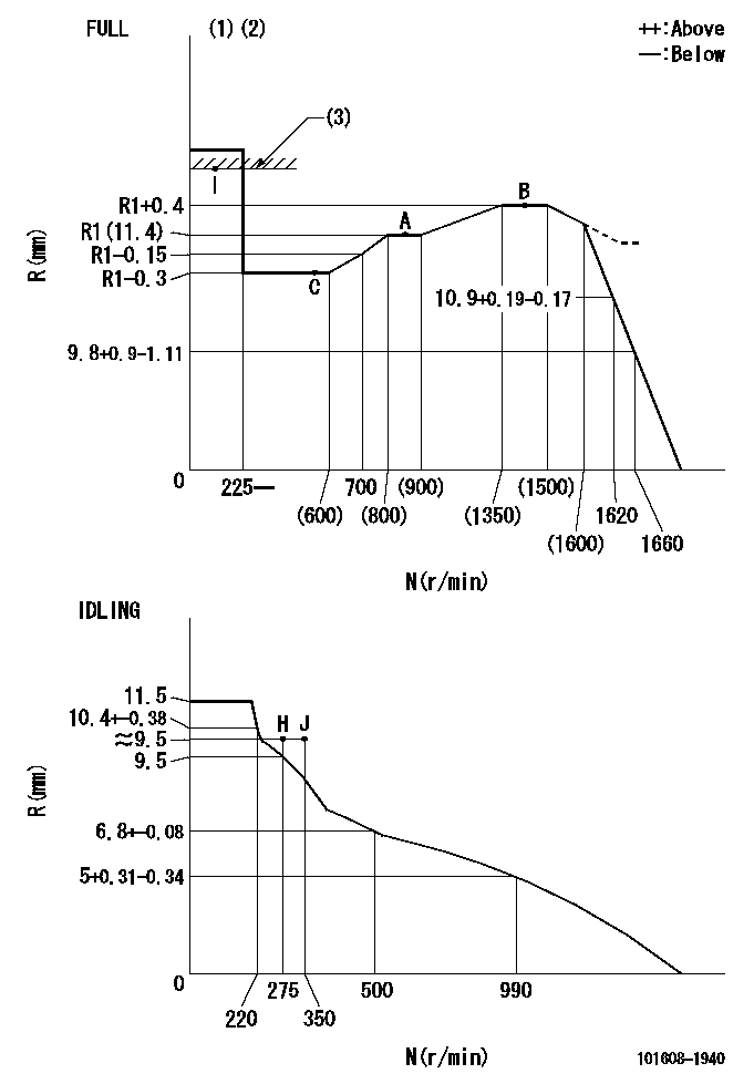
N:Pump speed
R:Rack position (mm)
(1)Torque cam stamping: T1
(2)Tolerance for racks not indicated: +-0.05mm.
(3)RACK LIMIT
----------
T1=M16
----------
----------
T1=M16
----------
Speed control lever angle
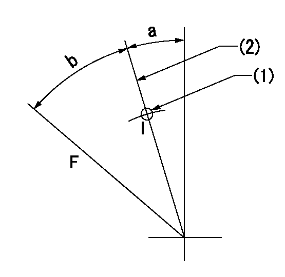
F:Full speed
I:Idle
(1)Use the hole at R = aa
(2)Stopper bolt set position 'H'
----------
aa=40mm
----------
a=18.5deg+-5deg b=42deg+-3deg
----------
aa=40mm
----------
a=18.5deg+-5deg b=42deg+-3deg
Stop lever angle
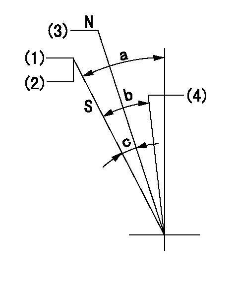
N:Engine manufacturer's normal use
S:Stop the pump.
(1)With the speed lever at Full, set the stopper bolt so that speed = aa and rack position = bb (non-injection rack position). Confirm non-injection.
(2)After setting the stopper bolt, confirm non-injection at speed cc. Rack position = dd (non-injection rack position).
(3)Rack position = approximately ee (speed lever full, speed = ff).
(4)Free (at delivery)
----------
aa=1450r/min bb=7.2-0.5mm cc=275r/min dd=(8)mm ee=15mm ff=0r/min
----------
a=36.5deg+-5deg b=(25deg) c=13deg+-5deg
----------
aa=1450r/min bb=7.2-0.5mm cc=275r/min dd=(8)mm ee=15mm ff=0r/min
----------
a=36.5deg+-5deg b=(25deg) c=13deg+-5deg
0000001501 LEVER
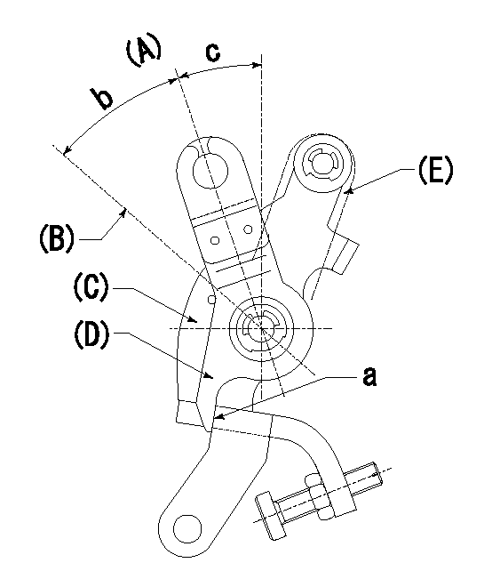
(A) Idle
(B) Full speed
(C) Base lever
(D) Accelerator lever
(E) Accelerator lever delivery position
1. Measure speed lever angle
(1)Measure the angle when the accelerator lever (D) contacted the base lever (C) at a.
----------
----------
b=42deg+-3deg c=18.5deg+-5deg
----------
----------
b=42deg+-3deg c=18.5deg+-5deg
Timing setting

(1)Pump vertical direction
(2)Position of timer's tooth at No 1 cylinder's beginning of injection
(3)B.T.D.C.: aa
(4)-
----------
aa=12deg
----------
a=(1deg)
----------
aa=12deg
----------
a=(1deg)
Information:
Important
Clean the oil supply line to the compressor and run the engine for a few seconds to be sure the oil supply is flowing freely.Connect oil and/or air pipes, ensuring that the air cleaner or filter is clean and properly installed.Check after Installation
With the compressor running, check for noisy operation and oil and air leaks.Dismantling
Marking before dismantling
The compressor should have the following items marked to show the correct relationship prior to dismantling.1. Position of cylinder head in relation to cylinder and crankcase.2. Position of end-cover(s) in relation to crankcase.3. Position of crankshaft in relation to crankcase.Removing and Dismantling Cylinder Head and Cylinder
Remove the unloader cap and copper washer and withdraw the unloader plunger assembly and spring.Remove the delivery valve cap and copper washer, and remove delivery valve spring and seat retaining spring.Unscrew the four nuts and washers from cylinder head studs and lift off cylinder head. Remove the joint.Remove the delivery valve and screw out the valve seat.Withdraw inlet valve spring guide. (A simple extractor can be made from two 1/4 in U.N.F. bolts and a strip of metal formed to bridge the guide). Remove the inlet valve spring, inlet valve and valve seat.Withdraw cylinder and remove the joint.Removing and Dismantling Piston and Connecting Rod Assemblies
Remove the compressor mounting bracket and joint.Turn the crankshaft to B.D.C. position and release the tabs of the locking strap. Unscrew the two bolts and remove the connecting rod cap. Withdraw piston assembly and replace connecting rod cap.Remove the piston rings from the piston. If the piston is to be detached from the connecting rod, release one gudgeon pin retaining circlip and press the gudgeon pin from the piston and connecting rod.Removing Crankshaft
Remove compressor drive gear.Remove drive key from crankshaft.Unscrew the four setscrews or nuts together with washers securing the rear end-cover to crankcase. Withdraw the end-cover, plain bearing, thrust washer and joint.Unscrew the four setscrews or nuts securing the drive end-cover, and withdraw the end-cover complete with crankshaft and joint. Tap crankshaft with bearing from drive end-cover.Cleaning
Ensure that all carbon is removed from the cylinder head. Check that the air passages in the head and the oilways in the crankcase, where applicable, rear end-cover and crankshaft are clear and clean.Clean inlet and discharge valves, not damaged or worn excessively, by lapping them on a sheet of crocus cloth held on a flat surface.Inspection of Parts
Cylinder
Check cylinder bore for excessive wear, out-of-round or scoring. If scored or out-of-round more than 0.002 in (0,05 mm) or tapered more than 0.003 in (0,08 mm) cylinder should be rebored. The original cylinder bore is to the limits 2.6255/2.6265 in (66,69/66,71 mm) and the clearance for the piston is 0.002/0.003 in (0,05/0,08 mm). Check for wear in cylinder bore and rectify in accordance with following table:-Piston and Connecting Rod
Inspect piston for scores, cracks or damage of any kind. Check fit of rings in ring grooves, clearance should be 0.0005/0.0025 in (0,01/0,06 mm). Install rings in cylinder and check that gaps are 0.002/0.007 in (0,08/0,18 mm). Check fit
Have questions with 101608-1940?
Group cross 101608-1940 ZEXEL
Mitsubishi
101608-1940
9 400 611 519
ME170446
INJECTION-PUMP ASSEMBLY
6D16
6D16