Information injection-pump assembly
BOSCH
9 400 615 825
9400615825
ZEXEL
101608-1870
1016081870
MITSUBISHI
ME078435
me078435
Rating:
Include in #2:
104746-5690
as _
Cross reference number
BOSCH
9 400 615 825
9400615825
ZEXEL
101608-1870
1016081870
MITSUBISHI
ME078435
me078435
Zexel num
Bosch num
Firm num
Name
101608-1870
9 400 615 825
ME078435 MITSUBISHI
INJECTION-PUMP ASSEMBLY
6D16TE K 14BF INJECTION PUMP ASSY PE6AD PE
6D16TE K 14BF INJECTION PUMP ASSY PE6AD PE
Calibration Data:
Adjustment conditions
Test oil
1404 Test oil ISO4113 or {SAEJ967d}
1404 Test oil ISO4113 or {SAEJ967d}
Test oil temperature
degC
40
40
45
Nozzle and nozzle holder
105780-8140
Bosch type code
EF8511/9A
Nozzle
105780-0000
Bosch type code
DN12SD12T
Nozzle holder
105780-2080
Bosch type code
EF8511/9
Opening pressure
MPa
17.2
Opening pressure
kgf/cm2
175
Injection pipe
Outer diameter - inner diameter - length (mm) mm 6-2-600
Outer diameter - inner diameter - length (mm) mm 6-2-600
Overflow valve
131424-5520
Overflow valve opening pressure
kPa
255
221
289
Overflow valve opening pressure
kgf/cm2
2.6
2.25
2.95
Tester oil delivery pressure
kPa
157
157
157
Tester oil delivery pressure
kgf/cm2
1.6
1.6
1.6
Direction of rotation (viewed from drive side)
Left L
Left L
Injection timing adjustment
Direction of rotation (viewed from drive side)
Left L
Left L
Injection order
1-5-3-6-
2-4
Pre-stroke
mm
4.5
4.45
4.55
Beginning of injection position
Governor side NO.1
Governor side NO.1
Difference between angles 1
Cal 1-5 deg. 60 59.5 60.5
Cal 1-5 deg. 60 59.5 60.5
Difference between angles 2
Cal 1-3 deg. 120 119.5 120.5
Cal 1-3 deg. 120 119.5 120.5
Difference between angles 3
Cal 1-6 deg. 180 179.5 180.5
Cal 1-6 deg. 180 179.5 180.5
Difference between angles 4
Cyl.1-2 deg. 240 239.5 240.5
Cyl.1-2 deg. 240 239.5 240.5
Difference between angles 5
Cal 1-4 deg. 300 299.5 300.5
Cal 1-4 deg. 300 299.5 300.5
Injection quantity adjustment
Adjusting point
A
Rack position
10.9
Pump speed
r/min
1100
1100
1100
Average injection quantity
mm3/st.
106.5
105.5
107.5
Max. variation between cylinders
%
0
-2.5
2.5
Basic
*
Fixing the lever
*
Injection quantity adjustment_02
Adjusting point
B
Rack position
8.3+-0.5
Pump speed
r/min
325
325
325
Average injection quantity
mm3/st.
10.5
9
12
Max. variation between cylinders
%
0
-15
15
Fixing the rack
*
Timer adjustment
Pump speed
r/min
0
Advance angle
deg.
1.5
1
2
Timer adjustment_02
Pump speed
r/min
-
Advance angle
deg.
1.5
1
2
Remarks
Measure speed (beginning of operation).
Measure speed (beginning of operation).
Timer adjustment_03
Pump speed
r/min
850
Advance angle
deg.
0
0
0
Remarks
Finish
Finish
Test data Ex:
Governor adjustment
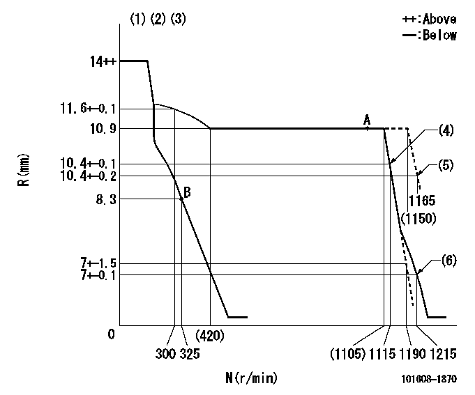
N:Pump speed
R:Rack position (mm)
(1)Notch fixed: K
(2)Tolerance for racks not indicated: +-0.05mm.
(3)Torque spring does not operate.
(4)Main spring setting
(5)Set at delivery
(6)Set idle sub-spring
----------
K=8
----------
----------
K=8
----------
Speed control lever angle
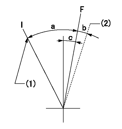
F:Full speed
I:Idle
(1)Stopper bolt setting
(2)At delivery
----------
----------
a=(20deg)+-5deg b=(2deg) c=(5deg)+-5deg
----------
----------
a=(20deg)+-5deg b=(2deg) c=(5deg)+-5deg
Stop lever angle

N:Pump normal
S:Stop the pump.
----------
----------
a=26deg+-5deg b=53deg+-5deg
----------
----------
a=26deg+-5deg b=53deg+-5deg
Timing setting

(1)Pump vertical direction
(2)Position of coupling's tooth at No 1 cylinder's beginning of injection
(3)B.T.D.C.: aa
(4)-
----------
aa=11deg
----------
a=(1deg)
----------
aa=11deg
----------
a=(1deg)
Information:
Installation procedure
Installation: Oil pan* Clean the sealant application surfaces of each part. * Apply a bead of sealant to each of the mating surfaces of the timing gear case, lower crankcase and front plate (at the two locations indicated the illustration). Installation: Oil pan* Clean the mating surfaces of each part. * Apply a bead of sealant to the mating surface of the oil pan evenly and without any breaks.* Mount the oil pan within three minutes of applying the sealant. Make sure that the sealant stays in place.
* Do not start the engine less than an hour after installation. If the oil pan mounting bolts were loosened or removed, be sure to reapply sealant.
Oil Pump
* Disassembly sequence1 Oil pump cover2 Driven gear3 Plug4 Relief valve spring5 Steel ball6 Gear and case7 O-ring*a Drive gear*b Oil pump gearP Locating pinX Non-reusable parts* Assembly sequenceFollow the disassembly procedure in reverse.Service standards (Unit: mm) Tightening torque (Unit: N m {kgf m}) Lubricant and/or sealant Inspection procedure
Inspection: Oil pump cover, driven gear, and gear and case* Measure the clearance between each gear's shaft and the oil pump cover, as well as between each gear's shaft and the gear and case. * If the measurements are not within the standard value range, replace the defective part(s). Inspection: Driven gear, drive gear and gear and case* Carry out the following inspection. Replace the oil pump if any defects are found. (1) Sinkage of each gear from gear and case end surface(2) Gear and case-to-tooth tip clearance for each gear Oil Cooler <Engine-Mounted Type, Engine Separately Mounted Type>, and Oil Filter <Engine-Mounted Type>
* Wipe up any spilled engine oil, as it can cause fires.* To avoid any risks of burns, take care not to touch the engine oil when the engine is hot.
* Make sure not to put any engine oil on the belt when working on the oil cooler and oil filter. Belt soiled with oil or grease may easily slip, resulting in deteriorated performance of the cooling system.* Do not reuse the oil filter elements by washing.
* Removal sequence1 Oil filter2 Plug3 Regulator valve spring4 Regulator valve5 Plug6 Bypass valve spring7 Bypass valve8 Oil cooler element9 Gasket10 Water drain plug11 Oil cooler body12 O-ring13 Gasket14 Water separate lipX Non-reusable parts* Installation sequenceFollow the removal sequence in reverse.Service standards (Unit: mm) Tightening torque (Unit: N m {kgf m}) Lubricant and/or sealant Special tools Removal procedure
Removal: Oil filter <Engine-mounted type> Inspection procedure
Inspection: Oil cooler element* Plug the outlet of the oil cooler element and connect a hose to the engine oil inlet port. Then, immerse the oil cooler element in a tank of water. * Apply an air pressure of 1.5 MPa {15 kgf/cm2} for 15 seconds through the hose, and check for any air leaks.* Replace the element if it leaks air.Installation procedure
Installation: Oil cooler <Engine-mounted type>* Clean the oil filter mounting surface of the oil cooler. * Apply a thin coat of engine oil on the oil filter gasket.* Screw in the
Have questions with 101608-1870?
Group cross 101608-1870 ZEXEL
Mitsubishi
Mitsubishi
101608-1870
9 400 615 825
ME078435
INJECTION-PUMP ASSEMBLY
6D16TE
6D16TE