Information injection-pump assembly
BOSCH
9 400 615 824
9400615824
ZEXEL
101608-1860
1016081860
MITSUBISHI
ME170418
me170418
Rating:
Include in #2:
104746-5681
as _
Cross reference number
BOSCH
9 400 615 824
9400615824
ZEXEL
101608-1860
1016081860
MITSUBISHI
ME170418
me170418
Zexel num
Bosch num
Firm num
Name
101608-1860
9 400 615 824
ME170418 MITSUBISHI
INJECTION-PUMP ASSEMBLY
6D17-2 K 14BF INJECTION PUMP ASSY PE6AD PE
6D17-2 K 14BF INJECTION PUMP ASSY PE6AD PE
Calibration Data:
Adjustment conditions
Test oil
1404 Test oil ISO4113 or {SAEJ967d}
1404 Test oil ISO4113 or {SAEJ967d}
Test oil temperature
degC
40
40
45
Nozzle and nozzle holder
105780-8140
Bosch type code
EF8511/9A
Nozzle
105780-0000
Bosch type code
DN12SD12T
Nozzle holder
105780-2080
Bosch type code
EF8511/9
Opening pressure
MPa
17.2
Opening pressure
kgf/cm2
175
Injection pipe
Outer diameter - inner diameter - length (mm) mm 6-2-600
Outer diameter - inner diameter - length (mm) mm 6-2-600
Overflow valve
131424-8420
Overflow valve opening pressure
kPa
255
221
289
Overflow valve opening pressure
kgf/cm2
2.6
2.25
2.95
Tester oil delivery pressure
kPa
157
157
157
Tester oil delivery pressure
kgf/cm2
1.6
1.6
1.6
Direction of rotation (viewed from drive side)
Left L
Left L
Injection timing adjustment
Direction of rotation (viewed from drive side)
Left L
Left L
Injection order
1-5-3-6-
2-4
Pre-stroke
mm
3.2
3.15
3.25
Beginning of injection position
Governor side NO.1
Governor side NO.1
Difference between angles 1
Cal 1-5 deg. 60 59.5 60.5
Cal 1-5 deg. 60 59.5 60.5
Difference between angles 2
Cal 1-3 deg. 120 119.5 120.5
Cal 1-3 deg. 120 119.5 120.5
Difference between angles 3
Cal 1-6 deg. 180 179.5 180.5
Cal 1-6 deg. 180 179.5 180.5
Difference between angles 4
Cyl.1-2 deg. 240 239.5 240.5
Cyl.1-2 deg. 240 239.5 240.5
Difference between angles 5
Cal 1-4 deg. 300 299.5 300.5
Cal 1-4 deg. 300 299.5 300.5
Injection quantity adjustment
Adjusting point
-
Rack position
11.9
Pump speed
r/min
850
850
850
Each cylinder's injection qty
mm3/st.
81.5
79.1
83.9
Basic
*
Fixing the rack
*
Standard for adjustment of the maximum variation between cylinders
*
Injection quantity adjustment_02
Adjusting point
Z
Rack position
9.5+-0.5
Pump speed
r/min
600
600
600
Each cylinder's injection qty
mm3/st.
10.8
9.2
12.4
Fixing the rack
*
Standard for adjustment of the maximum variation between cylinders
*
Injection quantity adjustment_03
Adjusting point
A
Rack position
R1(11.9)
Pump speed
r/min
850
850
850
Average injection quantity
mm3/st.
81.5
80.5
82.5
Basic
*
Fixing the lever
*
Injection quantity adjustment_04
Adjusting point
B
Rack position
R1+0.35
Pump speed
r/min
1450
1450
1450
Average injection quantity
mm3/st.
88
84
92
Fixing the lever
*
Injection quantity adjustment_05
Adjusting point
C
Rack position
R1-0.5
Pump speed
r/min
500
500
500
Average injection quantity
mm3/st.
59.5
55.5
63.5
Fixing the lever
*
Injection quantity adjustment_06
Adjusting point
I
Rack position
-
Pump speed
r/min
100
100
100
Average injection quantity
mm3/st.
95
85
105
Fixing the lever
*
Rack limit
*
Timer adjustment
Pump speed
r/min
950--
Advance angle
deg.
0
0
0
Remarks
Start
Start
Timer adjustment_02
Pump speed
r/min
900
Advance angle
deg.
0.5
Timer adjustment_03
Pump speed
r/min
-
Advance angle
deg.
1
0.5
1.5
Remarks
Measure the actual speed.
Measure the actual speed.
Timer adjustment_04
Pump speed
r/min
1100
Advance angle
deg.
1
0.5
1.5
Timer adjustment_05
Pump speed
r/min
1400
Advance angle
deg.
7
6.5
7.5
Remarks
Finish
Finish
Test data Ex:
Governor adjustment
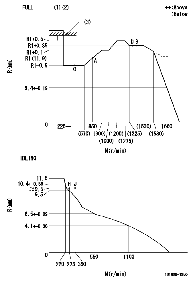
N:Pump speed
R:Rack position (mm)
(1)Torque cam stamping: T1
(2)Tolerance for racks not indicated: +-0.05mm.
(3)RACK LIMIT
----------
T1=L01
----------
----------
T1=L01
----------
Speed control lever angle

F:Full speed
I:Idle
(1)Stopper bolt set position 'H'
----------
----------
a=18.5deg+-5deg b=42deg+-3deg
----------
----------
a=18.5deg+-5deg b=42deg+-3deg
Stop lever angle
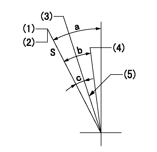
S:Stop the pump.
(1)Set the stopper bolt at pump speed = aa and rack position = bb (non-injection rack position). Confirm non-injection.
(2)After setting the stopper bolt, confirm non-injection at speed cc. Rack position = dd (non-injection rack position).
(3)Rack position = approximately ee (speed lever full, speed = ff).
(4)Free (at delivery)
(5)Normal use set at engine manufacturer.
----------
aa=1450r/min bb=7.2-0.5mm cc=275r/min dd=(8.8)mm ee=15mm ff=0r/min
----------
a=36.5deg+-5deg b=(25deg) c=13deg+-5deg
----------
aa=1450r/min bb=7.2-0.5mm cc=275r/min dd=(8.8)mm ee=15mm ff=0r/min
----------
a=36.5deg+-5deg b=(25deg) c=13deg+-5deg
0000001501 MICRO SWITCH
Adjust the bolt to obtain the following lever position when the micro-switch is ON.
1. Microswitch adjustment (OPEN type)
Confirm with the lever angle at full.
(1)Speed N1
(2)Rack position Ra
2. Idle side microswitch adjustment (OPEN type)
Confirm with the lever angle at idle.
(1)Speed N2
(2)Rack position Rb
----------
N1=1675r/min Ra=8.5+-0.1mm N2=275r/min Rb=9.7+-0.1mm
----------
----------
N1=1675r/min Ra=8.5+-0.1mm N2=275r/min Rb=9.7+-0.1mm
----------
0000001601 RACK SENSOR

V1:Supply voltage
V2f:Full side output voltage
V2i:Idle side output voltage
(A) Black
(B) Yellow
(C) Red
(D) Trimmer
(E): Shaft
(F) Nut
(G) Load lever
1. Load sensor adjustment
(1)Connect as shown in the above diagram and apply supply voltage V1.
(2)Hold the load lever (G) against the full side.
(3)Turn the shaft so that the voltage between (A) and (B) is V2.
(4)Hold the load lever (G) against the idle side.
(5)Adjust (D) so that the voltage between (A) and (B) is V2i.
(6)Repeat the above adjustments.
(7)Tighten the nut (F) at the point satisfying the standards.
(8)Hold the load lever against the full side stopper and the idle side stopper.
(9)At this time, confirm that the full side output voltage is V2f and the idle side output voltage is V2i.
----------
V1=3.57+-0.02V V2f=3+0.05V V2i=1+0.1V
----------
----------
V1=3.57+-0.02V V2f=3+0.05V V2i=1+0.1V
----------
0000001701 LEVER
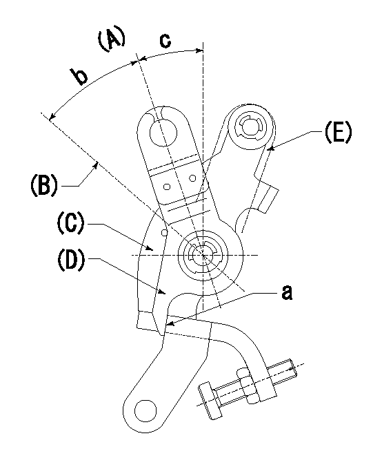
(A) Idle
(B) Full speed
(C) Base lever
(D) Accelerator lever
(E) Accelerator lever delivery position
1. Measure speed lever angle
(1)Measure the angle when the accelerator lever (D) contacted the base lever (C) at a.
----------
----------
b=42deg+-3deg c=18.5deg+-5deg
----------
----------
b=42deg+-3deg c=18.5deg+-5deg
Timing setting

(1)Pump vertical direction
(2)Position of timer's tooth at No 1 cylinder's beginning of injection
(3)B.T.D.C.: aa
(4)-
----------
aa=7deg
----------
a=(4deg)
----------
aa=7deg
----------
a=(4deg)
Information:
* Be sure to orient the oil grooves as indicated above, otherwise seizures may occur in the engine.
* Use oversize thrust plates when adjusting the crankshaft end play. The upper and lower thrust plates on the same side must be of the same size. The thrust plates on one side may differ in size from those on the other side. Installation: Main bearings
* The upper main bearing has an oil hole while the lower main bearing does not. Do not confuse the two, as incorrect installation can cause seizures in the engine.
* Select and use a main bearing set of a thickness that can accommodate the inside diameter of each main bearing fitting hole between the upper crankcase and lower crankcase and the diameter of the corresponding crankshaft journal. Select the appropriate main bearing set by one of the two following methods.(1) Measurement based selection* Mount the upper crankcase on the lower crankcase without fitting main bearings. * Tighten the main cap bolts to 20 N m {2.0 kgf m}.* Measure the inside diameter of the main bearing fitting hole between the upper crankcase and lower crankcase (vertically from one point), and the diameter of the crankshaft journal (vertically or horizontally from one point).* Select a main bearing set that matches the measurements from the table below. If the color identification mark is indiscernible, measure the thickness of the bearing walls and use the measurements in its place. (Unit: mm) (2) Color identification mark based method* The crankshaft, upper crankcase, and main bearing can be appropriately combined in the following ways according to their color identification marks: No. 1: Position of color identification mark on No. 1 journalNo. 2: Position of color identification mark on No. 2 journalNo. 3: Position of color identification mark on No. 3 journalNo. 4: Position of color identification mark on No. 4 journalNo. 5: Position of color identification mark on No. 5 journal Installation: Lower crankcase
* Before installing the main cap bolt, check the punch marks on each bolt's head. (Bolts with one or two punch marks can be reused.)* The punch marks indicate the number of times each main cap bolt has been tightened using the torque-turn tightening method. Any main cap bolt that already has three punch marks must be replaced.
* Clean the sealant application surfaces of each part. * Apply a bead of sealant to the upper crankcase evenly and without any breaks as shown in the illustration.* Install the lower crankcase within three minutes of applying the sealant to the upper crankcase, being careful not to dislodge the sealant.* Apply engine oil to the threads and seating surface under the head of each of the main cap bolts, and tighten the bolts to a torque of 20 N m {2.0 kgf m} in the order indicated in the illustration (1 to 10). * Then, tighten the main cap bolts further by 90 degrees in the same order.* Tighten them by another 90 degrees in the same order.* After completing
Have questions with 101608-1860?
Group cross 101608-1860 ZEXEL
Mitsubishi
Mitsubishi
101608-1860
9 400 615 824
ME170418
INJECTION-PUMP ASSEMBLY
6D17-2
6D17-2