Information injection-pump assembly
BOSCH
9 400 615 823
9400615823
ZEXEL
101608-1850
1016081850
MITSUBISHI
ME170416
me170416
Rating:
Include in #1:
101402-8310
as _
Cross reference number
BOSCH
9 400 615 823
9400615823
ZEXEL
101608-1850
1016081850
MITSUBISHI
ME170416
me170416
Zexel num
Bosch num
Firm num
Name
101608-1850
9 400 615 823
ME170416 MITSUBISHI
INJECTION-PUMP ASSEMBLY
6D16 K 14BF INJECTION PUMP ASSY PE6AD PE
6D16 K 14BF INJECTION PUMP ASSY PE6AD PE
Calibration Data:
Adjustment conditions
Test oil
1404 Test oil ISO4113 or {SAEJ967d}
1404 Test oil ISO4113 or {SAEJ967d}
Test oil temperature
degC
40
40
45
Nozzle and nozzle holder
105780-8140
Bosch type code
EF8511/9A
Nozzle
105780-0000
Bosch type code
DN12SD12T
Nozzle holder
105780-2080
Bosch type code
EF8511/9
Opening pressure
MPa
17.2
Opening pressure
kgf/cm2
175
Injection pipe
Outer diameter - inner diameter - length (mm) mm 6-2-600
Outer diameter - inner diameter - length (mm) mm 6-2-600
Overflow valve
131424-8420
Overflow valve opening pressure
kPa
255
221
289
Overflow valve opening pressure
kgf/cm2
2.6
2.25
2.95
Tester oil delivery pressure
kPa
157
157
157
Tester oil delivery pressure
kgf/cm2
1.6
1.6
1.6
Direction of rotation (viewed from drive side)
Left L
Left L
Injection timing adjustment
Direction of rotation (viewed from drive side)
Left L
Left L
Injection order
1-5-3-6-
2-4
Pre-stroke
mm
3.2
3.15
3.25
Beginning of injection position
Governor side NO.1
Governor side NO.1
Difference between angles 1
Cal 1-5 deg. 60 59.5 60.5
Cal 1-5 deg. 60 59.5 60.5
Difference between angles 2
Cal 1-3 deg. 120 119.5 120.5
Cal 1-3 deg. 120 119.5 120.5
Difference between angles 3
Cal 1-6 deg. 180 179.5 180.5
Cal 1-6 deg. 180 179.5 180.5
Difference between angles 4
Cyl.1-2 deg. 240 239.5 240.5
Cyl.1-2 deg. 240 239.5 240.5
Difference between angles 5
Cal 1-4 deg. 300 299.5 300.5
Cal 1-4 deg. 300 299.5 300.5
Injection quantity adjustment
Adjusting point
-
Rack position
11.7
Pump speed
r/min
850
850
850
Each cylinder's injection qty
mm3/st.
78
75.7
80.3
Basic
*
Fixing the rack
*
Standard for adjustment of the maximum variation between cylinders
*
Injection quantity adjustment_02
Adjusting point
Z
Rack position
10+-0.5
Pump speed
r/min
480
480
480
Each cylinder's injection qty
mm3/st.
21.8
18.5
25.1
Fixing the rack
*
Standard for adjustment of the maximum variation between cylinders
*
Injection quantity adjustment_03
Adjusting point
A
Rack position
R1(11.7)
Pump speed
r/min
850
850
850
Average injection quantity
mm3/st.
78
77
79
Basic
*
Fixing the lever
*
Injection quantity adjustment_04
Adjusting point
B
Rack position
R1+0.25
Pump speed
r/min
1450
1450
1450
Average injection quantity
mm3/st.
82.5
78.5
86.5
Fixing the lever
*
Injection quantity adjustment_05
Adjusting point
C
Rack position
R1-0.55
Pump speed
r/min
500
500
500
Average injection quantity
mm3/st.
51.5
47.5
55.5
Fixing the lever
*
Injection quantity adjustment_06
Adjusting point
I
Rack position
-
Pump speed
r/min
100
100
100
Average injection quantity
mm3/st.
115
115
135
Fixing the lever
*
Rack limit
*
Timer adjustment
Pump speed
r/min
950--
Advance angle
deg.
0
0
0
Remarks
Start
Start
Timer adjustment_02
Pump speed
r/min
900
Advance angle
deg.
0.5
Timer adjustment_03
Pump speed
r/min
-
Advance angle
deg.
1
0.5
1.5
Remarks
Measure the actual speed.
Measure the actual speed.
Timer adjustment_04
Pump speed
r/min
1200
Advance angle
deg.
1
0.5
1.5
Timer adjustment_05
Pump speed
r/min
1450
Advance angle
deg.
7
6.5
7.5
Remarks
Finish
Finish
Test data Ex:
Governor adjustment
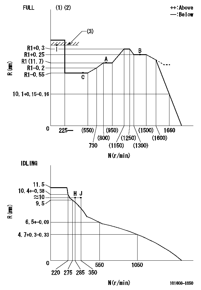
N:Pump speed
R:Rack position (mm)
(1)Torque cam stamping: T1
(2)Tolerance for racks not indicated: +-0.05mm.
(3)RACK LIMIT
----------
T1=M12
----------
----------
T1=M12
----------
Speed control lever angle

F:Full speed
I:Idle
(1)Use the hole at R = aa
(2)Stopper bolt set position 'H'
----------
aa=40mm
----------
a=21deg+-5deg b=38deg+-3deg
----------
aa=40mm
----------
a=21deg+-5deg b=38deg+-3deg
Stop lever angle
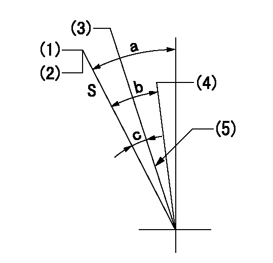
S:Stop the pump.
(1)Set the stopper bolt at pump speed = aa and rack position = bb (non-injection rack position). Confirm non-injection.
(2)After setting the stopper bolt, confirm non-injection at speed cc. Rack position = dd (non-injection rack position).
(3)Rack position = approximately ee (speed lever full, speed = ff).
(4)Free (at delivery)
(5)Normal use set at engine manufacturer.
----------
aa=1450r/min bb=7.2-0.5mm cc=275r/min dd=(8.8)mm ee=15mm ff=0r/min
----------
a=36.5deg+-5deg b=(25deg) c=13deg+-5deg
----------
aa=1450r/min bb=7.2-0.5mm cc=275r/min dd=(8.8)mm ee=15mm ff=0r/min
----------
a=36.5deg+-5deg b=(25deg) c=13deg+-5deg
0000001501 MICRO SWITCH
Adjust the bolt to obtain the following lever position when the micro-switch is ON.
1. Microswitch adjustment (OPEN type)
Confirm with the lever angle at full.
(1)Speed N1
(2)Rack position Ra
2. Idle side microswitch adjustment (OPEN type)
Confirm with the lever angle at idle.
(1)Speed N2
(2)Rack position Rb
----------
N1=1660r/min Ra=9.2+-0.1mm N2=285r/min Rb=10.2+-0.1mm
----------
----------
N1=1660r/min Ra=9.2+-0.1mm N2=285r/min Rb=10.2+-0.1mm
----------
0000001601 RACK SENSOR

V1:Supply voltage
V2f:Full side output voltage
V2i:Idle side output voltage
(A) Black
(B) Yellow
(C) Red
(D) Trimmer
(E): Shaft
(F) Nut
(G) Load lever
1. Load sensor adjustment
(1)Connect as shown in the above diagram and apply supply voltage V1.
(2)Hold the load lever (G) against the full side.
(3)Turn the shaft so that the voltage between (A) and (B) is V2.
(4)Hold the load lever (G) against the idle side.
(5)Adjust (D) so that the voltage between (A) and (B) is V2i.
(6)Repeat the above adjustments.
(7)Tighten the nut (F) at the point satisfying the standards.
(8)Hold the load lever against the full side stopper and the idle side stopper.
(9)At this time, confirm that the full side output voltage is V2f and the idle side output voltage is V2i.
----------
V1=3.57+-0.02V V2f=3+0.05V V2i=1+0.1V
----------
----------
V1=3.57+-0.02V V2f=3+0.05V V2i=1+0.1V
----------
0000001701 LEVER
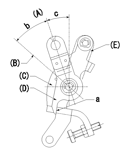
(A) Idle
(B) Full speed
(C) Base lever
(D) Accelerator lever
(E) Accelerator lever delivery position
1. Measure speed lever angle
(1)Measure the angle when the accelerator lever (D) contacted the base lever (C) at a.
----------
----------
b=38deg+-3deg c=21deg+-5deg
----------
----------
b=38deg+-3deg c=21deg+-5deg
Timing setting

(1)Pump vertical direction
(2)Position of timer's tooth at No 1 cylinder's beginning of injection
(3)B.T.D.C.: aa
(4)-
----------
aa=7deg
----------
a=(4deg)
----------
aa=7deg
----------
a=(4deg)
Information:
Precautions for Electrical System
* Before working on the electrical system, disconnect the (-) battery cable to prevent short circuits.
* Make sure the electrical equipment is OFF before disconnecting or connecting battery cable. Semiconductor components may otherwise be damaged.
* Carefully handle sensors relays, and other items that are sensitive to shock and heat. * When applying a voltage to a part for inspection purposes, check that the (+) and (-) cables are connected properly then gradually increase the voltage from zero. Do not exceed the specified voltage. Remember that sensors do not necessarily operate on the battery voltage. * When separating connectors, grasp the connectors themselves rather than the harnesses. * To separate locking connectors, first push them in the direction of the arrows. To reconnect locking connectors, push them together until they click.* Before washing the parts, cover electrical parts to keep them dry. (Use plastic sheets or the like.) Keep water away from harness connectors and sensors and immediately wipe off any water that gets on them. Handling precautions for electric circuits
* Do not pierce wire insulation with test probes or alligator clips when performing electrical inspections. Doing so can, particularly with the chassis harness, hasten corrosion.
(1) Inspection of harnesses (1.1) Inspections with connectors fitted together* Waterproof connectors* Connect an inspection harness and connector. A between the connectors B of the circuit to be inspected. Perform the inspection by applying a test probe C to the connectors of the inspection harness. Do not insert the test probe C into the wire-entry sides of the waterproof connectors since this would damage their waterproof seals and lead to rust. * Non-waterproof connectors* Perform the inspection by inserting a test probe C into the wire-entry sides of the connectors. An extra-narrow probe is required for control unit connectors, which are smaller than other types of connector. Do not force a regular-size probe into control unit connectors since this would cause damage. (1.2) Inspections with connectors separated* Inspections on female terminals* Perform the inspection by carefully inserting a test probe into the terminals. Do not force the test probe into the terminals since this could deform them and cause poor connections. * Inspections on male terminals* Perform the inspection by applying test probes directly to the pins.
* Be careful not to short-circuit pins together with the test probes. With control unit connectors, short-circuiting of pins can cause damage to the control unit's internal circuitry.
* When using a multimeter to check continuity, do not allow the test probes to touch the wrong terminals. (2) Inspection of connectors (2.1) Visual inspection* Check that the connectors are fitted together securely. * Check whether wires have been separated from their terminals due to pulling of the harness. * Check that male and female terminals fit together tightly. * Check for defective connections caused by loose terminals, by rust on terminals, or by contamination of terminals by foreign substances. (2.2) Checking for loose terminals* If connector terminal retainers become damaged, male and female terminals may not
Have questions with 101608-1850?
Group cross 101608-1850 ZEXEL
Mitsubishi
Mitsubishi
101608-1850
9 400 615 823
ME170416
INJECTION-PUMP ASSEMBLY
6D16
6D16