Information injection-pump assembly
BOSCH
9 400 615 821
9400615821
ZEXEL
101608-1830
1016081830
MITSUBISHI
ME219043
me219043

Rating:
Include in #2:
104742-1700
as _
Cross reference number
BOSCH
9 400 615 821
9400615821
ZEXEL
101608-1830
1016081830
MITSUBISHI
ME219043
me219043
Zexel num
Bosch num
Firm num
Name
101608-1830
9 400 615 821
ME219043 MITSUBISHI
INJECTION-PUMP ASSEMBLY
6D34T K
6D34T K
Calibration Data:
Adjustment conditions
Test oil
1404 Test oil ISO4113 or {SAEJ967d}
1404 Test oil ISO4113 or {SAEJ967d}
Test oil temperature
degC
40
40
45
Nozzle and nozzle holder
105780-8140
Bosch type code
EF8511/9A
Nozzle
105780-0000
Bosch type code
DN12SD12T
Nozzle holder
105780-2080
Bosch type code
EF8511/9
Opening pressure
MPa
17.2
Opening pressure
kgf/cm2
175
Injection pipe
Outer diameter - inner diameter - length (mm) mm 6-2-600
Outer diameter - inner diameter - length (mm) mm 6-2-600
Overflow valve
131424-5520
Overflow valve opening pressure
kPa
255
221
289
Overflow valve opening pressure
kgf/cm2
2.6
2.25
2.95
Tester oil delivery pressure
kPa
157
157
157
Tester oil delivery pressure
kgf/cm2
1.6
1.6
1.6
Direction of rotation (viewed from drive side)
Right R
Right R
Injection timing adjustment
Direction of rotation (viewed from drive side)
Right R
Right R
Injection order
1-5-3-6-
2-4
Pre-stroke
mm
3.5
3.45
3.55
Beginning of injection position
Drive side NO.1
Drive side NO.1
Difference between angles 1
Cal 1-5 deg. 60 59.5 60.5
Cal 1-5 deg. 60 59.5 60.5
Difference between angles 2
Cal 1-3 deg. 120 119.5 120.5
Cal 1-3 deg. 120 119.5 120.5
Difference between angles 3
Cal 1-6 deg. 180 179.5 180.5
Cal 1-6 deg. 180 179.5 180.5
Difference between angles 4
Cyl.1-2 deg. 240 239.5 240.5
Cyl.1-2 deg. 240 239.5 240.5
Difference between angles 5
Cal 1-4 deg. 300 299.5 300.5
Cal 1-4 deg. 300 299.5 300.5
Injection quantity adjustment
Adjusting point
A
Rack position
10.1
Pump speed
r/min
1000
1000
1000
Average injection quantity
mm3/st.
77
76
78
Max. variation between cylinders
%
0
-2.5
2.5
Basic
*
Fixing the lever
*
Injection quantity adjustment_02
Adjusting point
-
Rack position
7.6+-0.5
Pump speed
r/min
475
475
475
Average injection quantity
mm3/st.
8
6.7
9.3
Max. variation between cylinders
%
0
-14
14
Fixing the rack
*
Remarks
Adjust only variation between cylinders; adjust governor according to governor specifications.
Adjust only variation between cylinders; adjust governor according to governor specifications.
Injection quantity adjustment_03
Adjusting point
C
Rack position
-
Pump speed
r/min
100
100
100
Average injection quantity
mm3/st.
65
65
70
Fixing the lever
*
Rack limit
*
Timer adjustment
Pump speed
r/min
0
Advance angle
deg.
2
1.5
2.5
Timer adjustment_02
Pump speed
r/min
-
Advance angle
deg.
2
1.5
2.5
Remarks
Measure speed (beginning of operation).
Measure speed (beginning of operation).
Timer adjustment_03
Pump speed
r/min
700+-25
Advance angle
deg.
0
0
0
Remarks
Finish
Finish
Test data Ex:
Governor adjustment
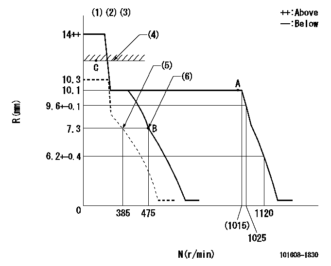
N:Pump speed
R:Rack position (mm)
(1)Target notch: K
(2)Tolerance for racks not indicated: +-0.05mm.
(3)Supplied with torque spring not set.
(4)RACK LIMIT
(5)Set idle sub-spring
(6)Main spring setting
----------
K=8
----------
----------
K=8
----------
Speed control lever angle

F:Full speed
I:Idle
(1)Stopper bolt setting
----------
----------
a=0deg+-5deg b=20deg+-5deg
----------
----------
a=0deg+-5deg b=20deg+-5deg
Stop lever angle

N:Pump normal
S:Stop the pump.
----------
----------
a=26.5deg+-5deg b=53deg+-5deg
----------
----------
a=26.5deg+-5deg b=53deg+-5deg
Timing setting

(1)Pump vertical direction
(2)Position of gear mark '3' at No 1 cylinder's beginning of injection
(3)B.T.D.C.: aa
(4)-
----------
aa=16deg
----------
a=(130deg)
----------
aa=16deg
----------
a=(130deg)
Information:
To Reassemble
1. Fit oil feed connection to rocker shaft and secure with the locating screw, ensuring that the screw enters the locating hole in the shaft.2. Refit the support brackets, springs, and rocker levers in the correct order (Fig. E.4). The support brackets are interchangeable and when fitting them ensure that the securing stud/setscrew holes are to the right viewing the shaft from the front end, with each pair of rockers inclined away from each other at the valve end.3. Fit securing washer and circlip to each end of the shaft.Push Rods
Check the push rods for straightness. If any are bent, fit replacements.Valve Stem Oil Seals
Where oversize valves are fitted, always ensure that correct size valve seals or 'O' rings are used.
E3 1. Collets2. Valve Spring Cap3. Oil Deflector4. Inner Valve Spring5. Outer Valve Spring6. Valve Spring Seat7. Exhaust Valve8. Inlet ValveAll hydraulically governed engines and certain mechanically governed engines have rubber oil deflectors fitted to inlet valve stems only (see Fig. E.3). When fitting these oil deflectors, the open end should be towards the cylinder head.With the majority of mechanically governed engines, oil seals are fitted to both inlet and exhaust valves. Earlier engines had a shallow rubber oil deflector fitted to the valve stems and positioned above the conical valve spring seating collar, the open end of the deflector being fitted towards the cylinder head. Later engines have a thin valve spring seating washer and a rubber oil seal which fits over the integral valve guide protrusion. In some cases, this latter seal has a nylon insert. The later sealing arrangement, due to a change in the diameter of the valve guide protrusion, is not interchangeable with the earlier sealing arrangement.On some engines, the seals are manufactured from Viton or silicon rubber material and they have a garter spring fitted around their outer circumference.In manufacturing, some engines have a red coloured material for inlet valve seals and black for exhaust valve seals. The red seal may only be fitted over the inlet valve. It is unsuitable for exhaust valves but the black seal may be fitted to either exhaust or inlet.The 4.2482 engine has a valve stem oil seal on both inlet and exhaust valves. The seals have garter springs round the seal neck for improved oil control.To Re-Assemble the Cylinder Head
1. Lightly oil valve stems.2. Fit valve to its correct guide or bore.3. Fit valve stem oil seals.4. Locate spring seat washers, valve springs and spring caps in position.5. Compress each valve spring and fit the valve collets.
E11, Valve Cap Sealing Arrangement As from Engine No. LD-----U778518H, 'O' ring seals have been fitted in the valve spring caps under the collets. The valve spring caps have been changed which have a deeper body so that the seal can be fitted as shown in Fig. E.11. The new caps are fitted to both valves, but the seals are fitted to exhaust valves only. T4.236 engines have two 'O' rings fitted in each valve spring cap.Cylinder Head
Have questions with 101608-1830?
Group cross 101608-1830 ZEXEL
Mitsubishi
Mitsubishi
101608-1830
9 400 615 821
ME219043
INJECTION-PUMP ASSEMBLY
6D34T
6D34T