Information injection-pump assembly
BOSCH
9 400 615 817
9400615817
ZEXEL
101608-1761
1016081761
MITSUBISHI
ME170302
me170302
Rating:
Include in #1:
107692-1800
as _
Cross reference number
BOSCH
9 400 615 817
9400615817
ZEXEL
101608-1761
1016081761
MITSUBISHI
ME170302
me170302
Zexel num
Bosch num
Firm num
Name
Calibration Data:
Adjustment conditions
Test oil
1404 Test oil ISO4113 or {SAEJ967d}
1404 Test oil ISO4113 or {SAEJ967d}
Test oil temperature
degC
40
40
45
Nozzle and nozzle holder
105780-8260
Bosch type code
9 430 610 133
Nozzle
105780-0120
Bosch type code
1 688 901 990
Nozzle holder
105780-2190
Opening pressure
MPa
18
Opening pressure
kgf/cm2
184
Injection pipe
Outer diameter - inner diameter - length (mm) mm 6-2-600
Outer diameter - inner diameter - length (mm) mm 6-2-600
Overflow valve
131424-8420
Overflow valve opening pressure
kPa
255
221
289
Overflow valve opening pressure
kgf/cm2
2.6
2.25
2.95
Tester oil delivery pressure
kPa
255
255
255
Tester oil delivery pressure
kgf/cm2
2.6
2.6
2.6
Direction of rotation (viewed from drive side)
Left L
Left L
Injection timing adjustment
Direction of rotation (viewed from drive side)
Left L
Left L
Injection order
1-5-3-6-
2-4
Pre-stroke
mm
3.2
3.15
3.25
Beginning of injection position
Governor side NO.1
Governor side NO.1
Difference between angles 1
Cal 1-5 deg. 60 59.5 60.5
Cal 1-5 deg. 60 59.5 60.5
Difference between angles 2
Cal 1-3 deg. 120 119.5 120.5
Cal 1-3 deg. 120 119.5 120.5
Difference between angles 3
Cal 1-6 deg. 180 179.5 180.5
Cal 1-6 deg. 180 179.5 180.5
Difference between angles 4
Cyl.1-2 deg. 240 239.5 240.5
Cyl.1-2 deg. 240 239.5 240.5
Difference between angles 5
Cal 1-4 deg. 300 299.5 300.5
Cal 1-4 deg. 300 299.5 300.5
Injection quantity adjustment
Adjusting point
-
Rack position
12.4
Pump speed
r/min
900
900
900
Each cylinder's injection qty
mm3/st.
110.5
107.2
113.8
Basic
*
Fixing the rack
*
Standard for adjustment of the maximum variation between cylinders
*
Injection quantity adjustment_02
Adjusting point
Z
Rack position
9.5+-0.5
Pump speed
r/min
275
275
275
Each cylinder's injection qty
mm3/st.
12.5
10.6
14.4
Fixing the rack
*
Standard for adjustment of the maximum variation between cylinders
*
Injection quantity adjustment_03
Adjusting point
A
Rack position
R1(12.4)
Pump speed
r/min
900
900
900
Average injection quantity
mm3/st.
110.5
109.5
111.5
Basic
*
Fixing the lever
*
Boost pressure
kPa
70.6
70.6
Boost pressure
mmHg
530
530
Injection quantity adjustment_04
Adjusting point
B
Rack position
R1+0.8
Pump speed
r/min
1400
1400
1400
Average injection quantity
mm3/st.
115.5
111.5
119.5
Fixing the lever
*
Boost pressure
kPa
70.6
70.6
Boost pressure
mmHg
530
530
Injection quantity adjustment_05
Adjusting point
C
Rack position
(R1+0.1)
Pump speed
r/min
500
500
500
Average injection quantity
mm3/st.
130.5
126.5
134.5
Fixing the lever
*
Boost pressure
kPa
70.6
70.6
Boost pressure
mmHg
530
530
Injection quantity adjustment_06
Adjusting point
D
Rack position
R2-1.35
Pump speed
r/min
400
400
400
Average injection quantity
mm3/st.
88
84
92
Fixing the lever
*
Boost pressure
kPa
0
0
0
Boost pressure
mmHg
0
0
0
Injection quantity adjustment_07
Adjusting point
I
Rack position
-
Pump speed
r/min
100
100
100
Average injection quantity
mm3/st.
160
160
170
Fixing the lever
*
Boost pressure
kPa
0
0
0
Boost pressure
mmHg
0
0
0
Rack limit
*
Boost compensator adjustment
Pump speed
r/min
400
400
400
Rack position
R2-1.35
Boost pressure
kPa
13.3
13.3
13.3
Boost pressure
mmHg
100
100
100
Boost compensator adjustment_02
Pump speed
r/min
400
400
400
Rack position
R2-0.55
Boost pressure
kPa
40
38.7
41.3
Boost pressure
mmHg
300
290
310
Boost compensator adjustment_03
Pump speed
r/min
400
400
400
Rack position
R2(R1+0.
1)
Boost pressure
kPa
57.3
57.3
57.3
Boost pressure
mmHg
430
430
430
Timer adjustment
Pump speed
r/min
(N1+50)-
-
Advance angle
deg.
0
0
0
Remarks
Start
Start
Timer adjustment_02
Pump speed
r/min
N1
Advance angle
deg.
0.5
Remarks
Measure the actual speed.
Measure the actual speed.
Timer adjustment_03
Pump speed
r/min
-
Advance angle
deg.
3.5
3.5
3.5
Remarks
Measure the actual speed, stop
Measure the actual speed, stop
Test data Ex:
Governor adjustment
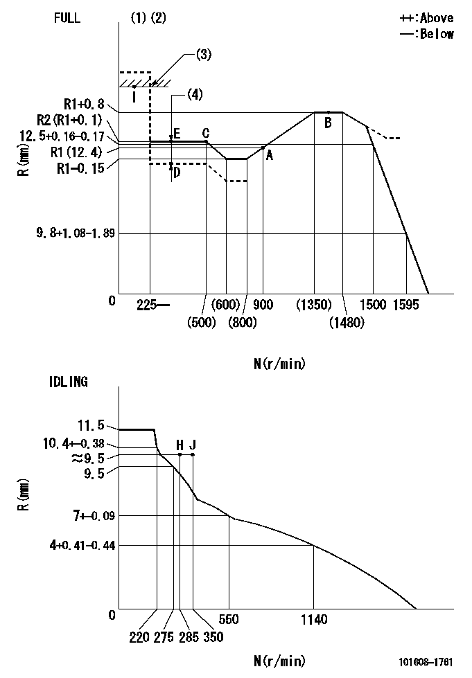
N:Pump speed
R:Rack position (mm)
(1)Torque cam stamping: T1
(2)Tolerance for racks not indicated: +-0.05mm.
(3)RACK LIMIT
(4)Boost compensator stroke: BCL
----------
T1=N21 BCL=1.35+-0.1mm
----------
----------
T1=N21 BCL=1.35+-0.1mm
----------
Speed control lever angle

F:Full speed
I:Idle
(1)Use the hole at R = aa
(2)Stopper bolt set position 'H'
----------
aa=40mm
----------
a=19deg+-5deg b=41.5deg+-3deg
----------
aa=40mm
----------
a=19deg+-5deg b=41.5deg+-3deg
Stop lever angle
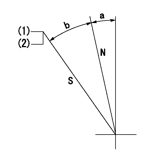
N:Pump normal
S:Stop the pump.
(1)With the speed lever at Full, set the stopper bolt so that speed = aa and rack position = bb (non-injection rack position). Confirm non-injection.
(2)After setting the stopper bolt at the speed lever's idle position, confirm that there is no injection at pump speed cc and rack position dd (non-injection rack position).
----------
aa=1400r/min bb=7-0.5mm cc=285r/min dd=(7.3)mm
----------
a=11.5deg+-5deg b=28deg+-5deg
----------
aa=1400r/min bb=7-0.5mm cc=285r/min dd=(7.3)mm
----------
a=11.5deg+-5deg b=28deg+-5deg
0000001501 LEVER
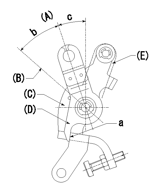
(A) Idle
(B) Full speed
(C) Base lever
(D) Accelerator lever
(E) Accelerator lever delivery position
1. Measure speed lever angle
(1)Measure the angle when the accelerator lever (D) contacted the base lever (C) at a.
----------
----------
b=41.5deg+-3deg c=19deg+-5deg
----------
----------
b=41.5deg+-3deg c=19deg+-5deg
Timing setting

(1)Pump vertical direction
(2)Position of timer's tooth at No 1 cylinder's beginning of injection
(3)B.T.D.C.: aa
(4)-
----------
aa=12deg
----------
a=(1deg)
----------
aa=12deg
----------
a=(1deg)
Information:
2-302. Dismantle the vee-belt idler or cover. Slacken the screw on the injection pump drive with special spanner No. 110310.Fig. 2-30
2-31
2-323. Slowly rotate the injection pump shaft in the direction of normal rotation until the pump starts to deliver fuel. (Use double spanner No. 110330 or a 19 mm socket spanner)Fig. 2-31 and 2-324. Check that fuel comes out from overflow pipe (when operating test unit or pump) only in droplets at intervals of 5-8 seconds.5. Retain the injection pump shaft in this position and tighten the screws on the injection pump drive, using special spanner No. 110310.6. Re-check the fuel-injection point and correct, if necessary. Turn off the high-pressure tester.
2-337. Assemble the vee-belt idler or cover with a new rubber O-ring. Dismantle the timing device. Connect the fuel lines, free from tension, and assemble the cover on the injection pump.Fig. 2-33Testing The Injection Nozzle (by testing outfit)
Injector is removed.
2-341. Connect injector to outfit.Fig. 2-34
2-352. With pressure gauge cut in, press outfit pump lever several times. Read opening pressure (Fig. 2-35) and inspect spray pattern. Compare readings with Specification Data. Important:At 25 - 30 bar below specified opening pressure, check that no fuel will dribble from nozzle.
2-363. Adjust nozzle opening pressure by shims below the spring (adding shims increases pressure and vice versa). Shims of the following thicknesses are available: 1.0; 1.05; 1.1; 1.15; etc. up to 1.95 mm.Fig. 2-36 Note for Refitment:By adding shims the pressure will be increased; by removing them the pressure will be decreased.
2-37For FL 912W, adjust release pressure by means of set-screw. By turning in screw, release pressure is increased; by turning it out, pressure is decreased.Fig. 2-37
2-384. Repeat test and recheck spray pattern. The jet(s) should be solid without surrounding mist. Fig. 2-38
2-39FL 912/W: one jet onlyFig. 2-395. Check that there is no after-dribble.6. If nozzle works unsatisfactorily, replace.Testing The Injection Pump (by special outfit)
The test is confined to making sure that the delivery valves and pump elements are free from leaks. The fuel feed pump intake is connected to the fuel tank or a receptacle containing filtered fuel. Proper fuel delivery is a prerequisite.
2-401. Disconnect injection line(s) on the fuel-injection pump. Evacuate the air from the fuel injection pump. Connect the tester to the pump element to be checked.Fig. 2-40
2-412. Open the second connection of the tester and evacuate the air. When the escaping fuel is free from bubbles, close the second connection.Fig. 2-41 The manual operation of the fuel-injection pump elements differs from one type of engine to another.F2L: Rotate the crankshaft until the air is evacuated or until the pressure has built up.
2-42As from 3 cylinder engine: Lower the tappet of the element to be checked by turning the crankshaft and then pump with a lever.Fig. 2-423. To check a pressure relief valve, generate a pressure of 150 bar. The indicator of the pressure gauge may not drop back more than 10 bar during a minute.
2-434. Generate a pressure peak of 350 bar. This must be clearly indicated by