Information injection-pump assembly
ZEXEL
101608-1760
1016081760

Rating:
Cross reference number
ZEXEL
101608-1760
1016081760
Zexel num
Bosch num
Firm num
Name
101608-1760
INJECTION-PUMP ASSEMBLY
Calibration Data:
Adjustment conditions
Test oil
1404 Test oil ISO4113 or {SAEJ967d}
1404 Test oil ISO4113 or {SAEJ967d}
Test oil temperature
degC
40
40
45
Nozzle and nozzle holder
105780-8260
Bosch type code
9 430 610 133
Nozzle
105780-0120
Bosch type code
1 688 901 990
Nozzle holder
105780-2190
Opening pressure
MPa
18
Opening pressure
kgf/cm2
184
Injection pipe
Outer diameter - inner diameter - length (mm) mm 6-2-600
Outer diameter - inner diameter - length (mm) mm 6-2-600
Overflow valve
131424-8420
Overflow valve opening pressure
kPa
255
221
289
Overflow valve opening pressure
kgf/cm2
2.6
2.25
2.95
Tester oil delivery pressure
kPa
255
255
255
Tester oil delivery pressure
kgf/cm2
2.6
2.6
2.6
Direction of rotation (viewed from drive side)
Left L
Left L
Injection timing adjustment
Direction of rotation (viewed from drive side)
Left L
Left L
Injection order
1-5-3-6-
2-4
Pre-stroke
mm
3.2
3.15
3.25
Beginning of injection position
Governor side NO.1
Governor side NO.1
Difference between angles 1
Cal 1-5 deg. 60 59.5 60.5
Cal 1-5 deg. 60 59.5 60.5
Difference between angles 2
Cal 1-3 deg. 120 119.5 120.5
Cal 1-3 deg. 120 119.5 120.5
Difference between angles 3
Cal 1-6 deg. 180 179.5 180.5
Cal 1-6 deg. 180 179.5 180.5
Difference between angles 4
Cyl.1-2 deg. 240 239.5 240.5
Cyl.1-2 deg. 240 239.5 240.5
Difference between angles 5
Cal 1-4 deg. 300 299.5 300.5
Cal 1-4 deg. 300 299.5 300.5
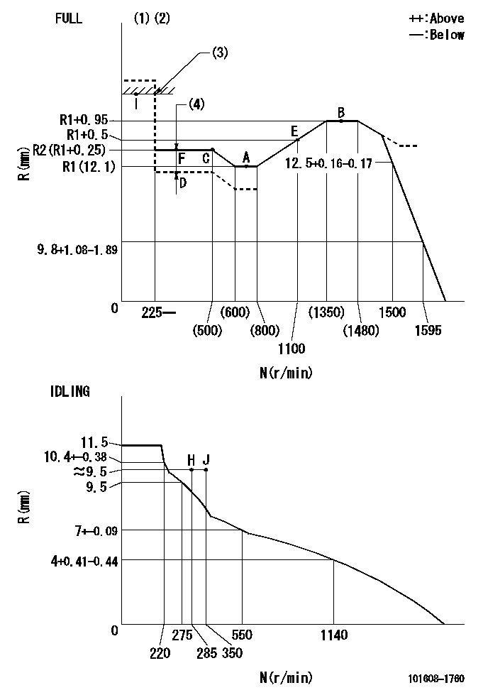
Injection quantity adjustment
Adjusting point
-
Rack position
12.1
Pump speed
r/min
700
700
700
Each cylinder's injection qty
mm3/st.
110
106.7
113.3
Basic
*
Fixing the rack
*
Standard for adjustment of the maximum variation between cylinders
*
Injection quantity adjustment_02
Adjusting point
Z
Rack position
9.5+-0.5
Pump speed
r/min
275
275
275
Each cylinder's injection qty
mm3/st.
12.5
10.6
14.4
Fixing the rack
*
Standard for adjustment of the maximum variation between cylinders
*
Injection quantity adjustment_03
Adjusting point
A
Rack position
R1(12.1)
Pump speed
r/min
700
700
700
Average injection quantity
mm3/st.
110
109
111
Basic
*
Fixing the lever
*
Boost pressure
kPa
70.6
70.6
Boost pressure
mmHg
530
530
Injection quantity adjustment_04
Adjusting point
B
Rack position
R1+0.95
Pump speed
r/min
1400
1400
1400
Average injection quantity
mm3/st.
114
110
118
Fixing the lever
*
Boost pressure
kPa
70.6
70.6
Boost pressure
mmHg
530
530
Injection quantity adjustment_05
Adjusting point
C
Rack position
(R1+0.25
)
Pump speed
r/min
500
500
500
Average injection quantity
mm3/st.
127.5
123.5
131.5
Fixing the lever
*
Boost pressure
kPa
70.6
70.6
Boost pressure
mmHg
530
530
Injection quantity adjustment_06
Adjusting point
D
Rack position
R2-1.35
Pump speed
r/min
400
400
400
Average injection quantity
mm3/st.
84.5
80.5
88.5
Fixing the lever
*
Boost pressure
kPa
0
0
0
Boost pressure
mmHg
0
0
0
Injection quantity adjustment_07
Adjusting point
I
Rack position
-
Pump speed
r/min
100
100
100
Average injection quantity
mm3/st.
160
160
170
Fixing the lever
*
Boost pressure
kPa
0
0
0
Boost pressure
mmHg
0
0
0
Rack limit
*
Injection quantity adjustment_08
Adjusting point
E
Rack position
R1+0.5
Pump speed
r/min
1100
1100
1100
Average injection quantity
mm3/st.
110
106
114
Fixing the lever
*
Boost pressure
kPa
70.6
70.6
Boost pressure
mmHg
530
530
Boost compensator adjustment
Pump speed
r/min
400
400
400
Rack position
R2-1.35
Boost pressure
kPa
13.3
12
14.6
Boost pressure
mmHg
100
90
110
Boost compensator adjustment_02
Pump speed
r/min
400
400
400
Rack position
R2(R1+0.
25)
Boost pressure
kPa
57.3
57.3
57.3
Boost pressure
mmHg
430
430
430
Timer adjustment
Pump speed
r/min
1000--
Advance angle
deg.
0
0
0
Remarks
Start
Start
Timer adjustment_02
Pump speed
r/min
950
Advance angle
deg.
0.5
Timer adjustment_03
Pump speed
r/min
1400
Advance angle
deg.
3.5
3
4
Remarks
Finish
Finish
Test data Ex:
Governor adjustment
N:Pump speed
R:Rack position (mm)
(1)Torque cam stamping: T1
(2)Tolerance for racks not indicated: +-0.05mm.
(3)RACK LIMIT
(4)Boost compensator stroke: BCL
----------
T1=N21 BCL=1.35+-0.1mm
----------
----------
T1=N21 BCL=1.35+-0.1mm
----------
Speed control lever angle

F:Full speed
I:Idle
(1)Use the hole at R = aa
(2)Stopper bolt set position 'H'
----------
aa=40mm
----------
a=19deg+-5deg b=41.5deg+-3deg
----------
aa=40mm
----------
a=19deg+-5deg b=41.5deg+-3deg
Stop lever angle
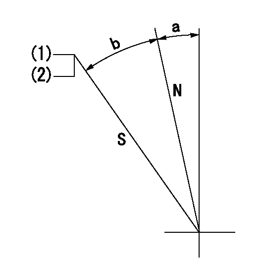
N:Pump normal
S:Stop the pump.
(1)With the speed lever at Full, set the stopper bolt so that speed = aa and rack position = bb (non-injection rack position). Confirm non-injection.
(2)After setting the stopper bolt at the speed lever's idle position, confirm that there is no injection at pump speed cc and rack position dd (non-injection rack position).
----------
aa=1400r/min bb=7-0.5mm cc=285r/min dd=(8.4)mm
----------
a=11.5deg+-5deg b=28deg+-5deg
----------
aa=1400r/min bb=7-0.5mm cc=285r/min dd=(8.4)mm
----------
a=11.5deg+-5deg b=28deg+-5deg
0000001501 LEVER
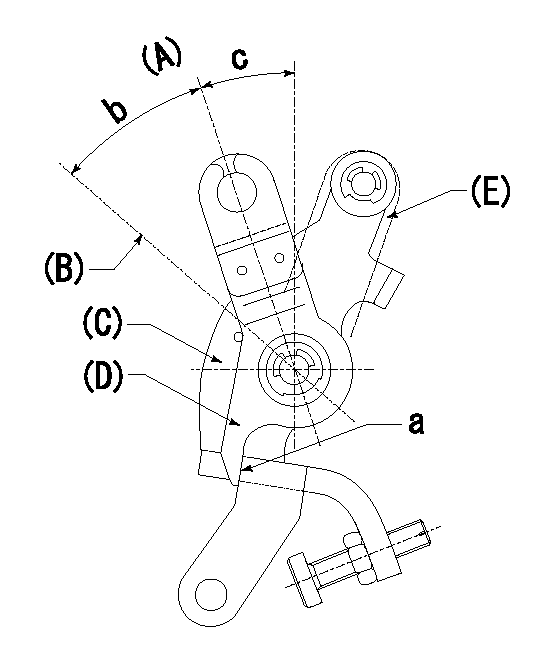
(A) Idle
(B) Full speed
(C) Base lever
(D) Accelerator lever
(E) Accelerator lever delivery position
1. Measure speed lever angle
(1)Measure the angle when the accelerator lever (D) contacted the base lever (C) at a.
----------
----------
b=41.5deg+-3deg c=19deg+-5deg
----------
----------
b=41.5deg+-3deg c=19deg+-5deg
Timing setting

(1)Pump vertical direction
(2)Position of timer's tooth at No 1 cylinder's beginning of injection
(3)B.T.D.C.: aa
(4)-
----------
aa=13deg
----------
a=(1deg)
----------
aa=13deg
----------
a=(1deg)
Information:
Engine Serial Numbers
1-1The serial No. is stamped both on the maker's nameplate (Fig. 1-1) and the crankcase.
1-3Engines of the F3/4/5/6L type have the serial number stamped at the back of the oil filler neck, on the flange for mounting the housing of the fuel injection pump.Fig. 1-3Maker's Nameplate
In addition to the engine serial No., the plate indicates the particular engine model and version respectively. Typical example BF6L 913 C:B = Engine with turbochargerF = Automotive or industrial engine6 = Number of cylindersL = Air-cooled9 = Number of series13 = Stroke of piston in cmThe suffix letters of the engine model designation mean:C = With charge air coolerG = Engine for fork-lift truckT = Mildly turbochargedW = Two-stage combustion system (swirl chamber)Further data of the nameplate:Rated power in kW (HP) and speed in rev/min. Letter "A" denotes continuous power (with overload capacity), both according to DIN 6270.De-rated industrial engines have an additional rating plate.The rating for automotive engines refers to DIN 70020.General Notes On Repair
To be successful, every repair job calls for precision workmanship, in clean and neat surroundings.
1-5The "front end" of the engine is understood to be the end opposite the flywheel, and the other engine faces are designated accordingly. Thus: Cylinder No. 1 is at the rear end = at the flywheel end. The cylinder numbers are applied to the crankcase, below the cylinder seating area. The sense of rotation of the engine is anti-clockwise, when facing the flywheel.Fig. 1-5
1-6The parts of the crankshaft assembly, timing gear, cylinders, pistons and cylinder heads should be numbered in sequence, unless they are already marked. The numbering should commence at the flywheel end.Fig. 1-6As the parts are dismantled, place them where they will not get damaged. Components that are subject to wear should be kept apart and should be gauged individually. If the low tolerances are exceeded, the components have to be replaced or rectified. In any case, fit new gaskets, packings and O-seals.The numbers of spare parts should be taken from the part number catalogue for the respective engine type. A good repair job that is to ensure satisfactory engine performance essentially calls for the use of genuine DEUTZ spare parts.Should bearing or pistons be damaged, the crankshaft and connecting rods should be inspected for cracks, if possible by the Magnaflux testing method. It is very important that the cause of the damage is established. Testing, repairs and/or reworking can be undertaken by the manufacturers or their appointed repair shops.
1-8For the repair work to be carried out on the removed engine, mounting on a swivelling assembly stand, special fixture No. 6067, is recommended.Fig. 1-8Tightening Instructions For Bolts And Studs
All bolts and studs tabulated shall first be hand-tightened to approx 30 Nm and then locked down alternately in stages until the specified angle degrees are obtained. Before assembling the bolts and studs, wet the threads and the bearing faces of the heads with motor oil. 1. Preloading
1-9Hold wrench so the thumb touches the end.Fig. 1-9Use a torque wrench for torques
Have questions with 101608-1760?
Group cross 101608-1760 ZEXEL
Mitsubishi
Mitsubishi
Mitsubishi
Mitsubishi
Mitsubishi
101608-1760
INJECTION-PUMP ASSEMBLY