Information injection-pump assembly
BOSCH
9 400 610 760
9400610760
ZEXEL
101608-1560
1016081560
MITSUBISHI
ME072805
me072805
Rating:
Service parts 101608-1560 INJECTION-PUMP ASSEMBLY:
1.
_
6.
COUPLING PLATE
7.
COUPLING PLATE
8.
_
9.
_
11.
Nozzle and Holder
ME076787
12.
Open Pre:MPa(Kqf/cm2)
21.6{220}
15.
NOZZLE SET
Cross reference number
BOSCH
9 400 610 760
9400610760
ZEXEL
101608-1560
1016081560
MITSUBISHI
ME072805
me072805
Zexel num
Bosch num
Firm num
Name
101608-1560
9 400 610 760
ME072805 MITSUBISHI
INJECTION-PUMP ASSEMBLY
6D16T K
6D16T K
Calibration Data:
Adjustment conditions
Test oil
1404 Test oil ISO4113 or {SAEJ967d}
1404 Test oil ISO4113 or {SAEJ967d}
Test oil temperature
degC
40
40
45
Nozzle and nozzle holder
105780-8140
Bosch type code
EF8511/9A
Nozzle
105780-0000
Bosch type code
DN12SD12T
Nozzle holder
105780-2080
Bosch type code
EF8511/9
Opening pressure
MPa
17.2
Opening pressure
kgf/cm2
175
Injection pipe
Outer diameter - inner diameter - length (mm) mm 6-2-600
Outer diameter - inner diameter - length (mm) mm 6-2-600
Overflow valve
131424-5520
Overflow valve opening pressure
kPa
255
221
289
Overflow valve opening pressure
kgf/cm2
2.6
2.25
2.95
Tester oil delivery pressure
kPa
157
157
157
Tester oil delivery pressure
kgf/cm2
1.6
1.6
1.6
Direction of rotation (viewed from drive side)
Left L
Left L
Injection timing adjustment
Direction of rotation (viewed from drive side)
Left L
Left L
Injection order
1-5-3-6-
2-4
Pre-stroke
mm
4.2
4.15
4.25
Beginning of injection position
Governor side NO.1
Governor side NO.1
Difference between angles 1
Cal 1-5 deg. 60 59.5 60.5
Cal 1-5 deg. 60 59.5 60.5
Difference between angles 2
Cal 1-3 deg. 120 119.5 120.5
Cal 1-3 deg. 120 119.5 120.5
Difference between angles 3
Cal 1-6 deg. 180 179.5 180.5
Cal 1-6 deg. 180 179.5 180.5
Difference between angles 4
Cyl.1-2 deg. 240 239.5 240.5
Cyl.1-2 deg. 240 239.5 240.5
Difference between angles 5
Cal 1-4 deg. 300 299.5 300.5
Cal 1-4 deg. 300 299.5 300.5
Injection quantity adjustment
Adjusting point
-
Rack position
13
Pump speed
r/min
700
700
700
Each cylinder's injection qty
mm3/st.
96.8
93.9
99.7
Basic
*
Fixing the rack
*
Standard for adjustment of the maximum variation between cylinders
*
Injection quantity adjustment_02
Adjusting point
H
Rack position
9.5+-0.5
Pump speed
r/min
275
275
275
Each cylinder's injection qty
mm3/st.
10.2
8.7
11.7
Fixing the rack
*
Standard for adjustment of the maximum variation between cylinders
*
Injection quantity adjustment_03
Adjusting point
A
Rack position
R1(13)
Pump speed
r/min
700
700
700
Average injection quantity
mm3/st.
96.8
95.8
97.8
Basic
*
Fixing the lever
*
Boost pressure
kPa
33.3
33.3
Boost pressure
mmHg
250
250
Injection quantity adjustment_04
Adjusting point
B
Rack position
(R1-0.35
)+0.05-0
.1
Pump speed
r/min
1400
1400
1400
Average injection quantity
mm3/st.
100.3
96.3
104.3
Fixing the lever
*
Boost pressure
kPa
33.3
33.3
Boost pressure
mmHg
250
250
Injection quantity adjustment_05
Adjusting point
C
Rack position
R2-0.6
Pump speed
r/min
300
300
300
Average injection quantity
mm3/st.
66.9
62.9
70.9
Fixing the lever
*
Boost pressure
kPa
0
0
0
Boost pressure
mmHg
0
0
0
Injection quantity adjustment_06
Adjusting point
D
Rack position
R2(R1+0.
25)
Pump speed
r/min
500
500
500
Average injection quantity
mm3/st.
96.5
92.5
100.5
Fixing the lever
*
Boost pressure
kPa
33.3
33.3
Boost pressure
mmHg
250
250
Injection quantity adjustment_07
Adjusting point
I
Rack position
-
Pump speed
r/min
100
100
100
Average injection quantity
mm3/st.
95
75
115
Fixing the lever
*
Boost pressure
kPa
0
0
0
Boost pressure
mmHg
0
0
0
Rack limit
*
Boost compensator adjustment
Pump speed
r/min
450
450
450
Rack position
R2-0.6
Boost pressure
kPa
6
4.7
7.3
Boost pressure
mmHg
45
35
55
Boost compensator adjustment_02
Pump speed
r/min
450
450
450
Rack position
R2(R1+0.
25)
Boost pressure
kPa
20
20
20
Boost pressure
mmHg
150
150
150
Timer adjustment
Pump speed
r/min
700--
Advance angle
deg.
0
0
0
Remarks
Start
Start
Timer adjustment_02
Pump speed
r/min
650
Advance angle
deg.
0.5
Timer adjustment_03
Pump speed
r/min
1400
Advance angle
deg.
3.5
3
4
Remarks
Finish
Finish
Test data Ex:
Governor adjustment
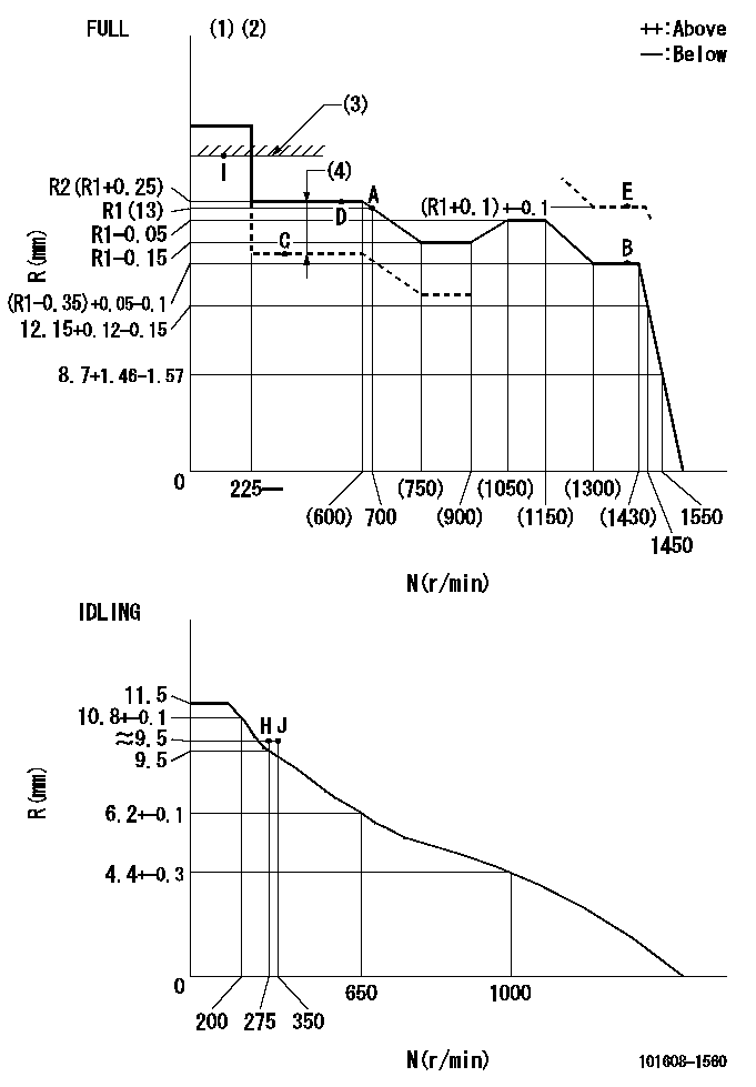
N:Pump speed
R:Rack position (mm)
(1)Torque cam stamping: T1
(2)Tolerance for racks not indicated: +-0.05mm.
(3)RACK LIMIT
(4)Boost compensator stroke: BCL
----------
T1=D24 BCL=0.6+-0.1mm
----------
----------
T1=D24 BCL=0.6+-0.1mm
----------
Speed control lever angle
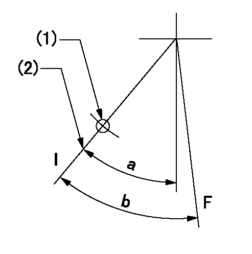
F:Full speed
I:Idle
(1)Use the hole at R = aa
(2)Stopper bolt set position 'H'
----------
aa=35mm
----------
a=33deg+-5deg b=(39deg)+-3deg
----------
aa=35mm
----------
a=33deg+-5deg b=(39deg)+-3deg
Stop lever angle
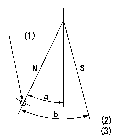
N:Pump normal
S:Stop the pump.
(1)Use the hole at R = aa
(2)Set the stopper bolt at speed = bb and rack position = cc (non-injection rack position). Confirm non-injection.
(3)After setting the stopper bolt, confirm non-injection at speed dd. Rack position = ee (non-injection rack position)
----------
aa=50mm bb=1400r/min cc=6.5-0.5mm dd=275r/min ee=(8.6)-0.5mm
----------
a=25deg+-5deg b=27deg+-5deg
----------
aa=50mm bb=1400r/min cc=6.5-0.5mm dd=275r/min ee=(8.6)-0.5mm
----------
a=25deg+-5deg b=27deg+-5deg
0000001501 TAMPER PROOF
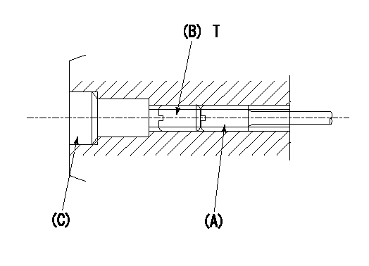
1. Method for setting tamperproof proofing
(1)After governor adjustment (torque cam phase adjustment), move the load lever to increase the full rack position to Ra.
(2)At pump speed N1, push in the screw (A) until the rack position is Rb.
(3)Temporarily caulk using the tip of a screwdriver
(4)Confirm that the rack at that time is at Rc.
(5)Lock using setscrew (B). (Tightening torque = T)
(6)Next, coat (C) with adhesive and then pressfit.
(7)Then, readjust the full rack position using the load lever.
----------
N1=1400r/min Ra=(0.4)mm Rb=(R1(13)+0.1)+-0.1mm Rc=(R1(13)+0.1)+-0.1mm
----------
T=4.9~7N-m(0.5~0.7Kgf-m)
----------
N1=1400r/min Ra=(0.4)mm Rb=(R1(13)+0.1)+-0.1mm Rc=(R1(13)+0.1)+-0.1mm
----------
T=4.9~7N-m(0.5~0.7Kgf-m)
0000001601 MICRO SWITCH
Adjustment of the micro-switch
Adjust the bolt to obtain the following lever position when the micro-switch is ON.
(1)Speed N1
(2)Rack position Ra
----------
N1=400r/min Ra=9.2+-0.1mm
----------
----------
N1=400r/min Ra=9.2+-0.1mm
----------
Timing setting

(1)Pump vertical direction
(2)Position of timer's tooth at No 1 cylinder's beginning of injection
(3)B.T.D.C.: aa
(4)-
----------
aa=12deg
----------
a=(1deg)
----------
aa=12deg
----------
a=(1deg)
Information:
Tooling, Test, and Bulk Ground Fill Support Equipment
Diesel Exhaust Fluid (DEF)
Two container sizes of DEF are available through the Cat® dealers in North America. DEF must meet ISO 22241-1 specifications.
Table 1
Tool Part Number Description
350-8733 Diesel Exhaust Fluid 9.5 L (2.5 US gal) bottle
350-8734 Diesel Exhaust Fluid 1378 L (364 US gal) tote
443-0955 Removal Tool DEF filter removal tool Dispensing Equipment
Three different dispensing kits are offered to protect DEF quality. Optional flow meter and coupler are also available.
Table 2
Tool Part Number Description
422-1185 Pump Adapter (DEF DISPENSER) 12 V dispenser unit
423-7843 Pump Adapter (DEF DISPENSER) 110 V dispenser unit
423-7844 Pump Adapter (DEF DISPENSER) 230 V dispenser unit with"smart start"tote base
423-7795 Flow Meter In line DEF flow meter
423-7799 Coupler MicroMatic coupler Dispenser Unit Repair Parts
Table 3
Tool Part Number Description
436-6643 Repair Kit 12 V dispenser unit
436-6646 Diesel Exhaust Fluid Pump 12 V repair group
436-6642 Hose 20'/4'
436-6644 Swivel
436-6645 Repair Kit 1/2 hp pump
436-6647 Nozzle (DIESEL EXHAUST FLUID) Dispensing nozzle Storage and Transportation
Preventing DEF contamination does not stop at the pump. Protect your DEF supply with climate-specific enclosures and transportation tanks.
Table 4
Part Number Description
435-8671 Dispenser Warm-weather enclosure
435-8672 Dispenser Cold-weather enclosure
460-4077 Tank 121 L (32 US gal)
460-4078 Tank 269 L (71 US gal) Fast Fill Vehicle Interface
Illustration 1 g06516654
584-9979 Nozzle As
Table 5
584-9979 Nozzle As
Repair parts for 584-9979 Nozzle As
- 587-3371 Rear Cap
- 587-3372 Handle
- 587-3373 Hose (3/4")
- 587-3374 O-Ring Seal
- 587-3375 Handle (optional)
459-9296 Receiver As (Permanently mounted on vehicle)
For heated DEF hose repair connectors, kits, and instructions , refer to Service Magazine, M0103829, "Repair Kits for Quick Connect Diesel Exhaust Fluid (DEF) Line Fittings Are Now Available for Certain Cat® Machine Engines". Testing Equipment
Test your DEF supply and DEF injector with DEF-specific testing equipment. Complete kits or individual testing components are available for your needs.
Table 6
441-0451 Tool Gp (includes hard case, foam insert, and hardware)
- 441-0454 Container
- 443-7055 Test Kit
- 398-4985 Probe
- 398-4987 Probe
- 398-5080 Lead
- 398-5081 Lead
- 398-5083 Plug
450-1515 Tool Gp (DIESEL EXHAUST FLUID) (includes hard case, foam insert, and hardware)
- 441-0454 Container
- 398-4985 Probe
- 398-4987 Probe
- 398-5080 Lead
- 398-5081 Lead
- 398-5083 Plug
441-0454 Container
443-7055 Test Kit
431-7087 Tool Gp (REFRACTOMETER (DEF))
360-0774 Refractometer
372-5260 Test Lead Tool Group
576-6134 Test Strip
Have questions with 101608-1560?
Group cross 101608-1560 ZEXEL
Mitsubishi
Mitsubishi
Mitsubishi
Mitsubishi
101608-1560
9 400 610 760
ME072805
INJECTION-PUMP ASSEMBLY
6D16T
6D16T
