Information injection-pump assembly
BOSCH
9 400 610 757
9400610757
ZEXEL
101608-1473
1016081473
MITSUBISHI
ME072742
me072742
Rating:
Service parts 101608-1473 INJECTION-PUMP ASSEMBLY:
1.
_
6.
COUPLING PLATE
7.
COUPLING PLATE
8.
_
9.
_
11.
Nozzle and Holder
ME072745
12.
Open Pre:MPa(Kqf/cm2)
15.7{160}/21.6{220}
14.
NOZZLE
Cross reference number
BOSCH
9 400 610 757
9400610757
ZEXEL
101608-1473
1016081473
MITSUBISHI
ME072742
me072742
Zexel num
Bosch num
Firm num
Name
101608-1473
9 400 610 757
ME072742 MITSUBISHI
INJECTION-PUMP ASSEMBLY
6D16T2 K 14BF INJECTION PUMP ASSY PE6AD PE
6D16T2 K 14BF INJECTION PUMP ASSY PE6AD PE
Calibration Data:
Adjustment conditions
Test oil
1404 Test oil ISO4113 or {SAEJ967d}
1404 Test oil ISO4113 or {SAEJ967d}
Test oil temperature
degC
40
40
45
Nozzle and nozzle holder
105780-8260
Bosch type code
9 430 610 133
Nozzle
105780-0120
Bosch type code
1 688 901 990
Nozzle holder
105780-2190
Opening pressure
MPa
18
Opening pressure
kgf/cm2
184
Injection pipe
Outer diameter - inner diameter - length (mm) mm 6-2-600
Outer diameter - inner diameter - length (mm) mm 6-2-600
Overflow valve
131424-8420
Overflow valve opening pressure
kPa
255
221
289
Overflow valve opening pressure
kgf/cm2
2.6
2.25
2.95
Tester oil delivery pressure
kPa
255
255
255
Tester oil delivery pressure
kgf/cm2
2.6
2.6
2.6
Direction of rotation (viewed from drive side)
Left L
Left L
Injection timing adjustment
Direction of rotation (viewed from drive side)
Left L
Left L
Injection order
1-5-3-6-
2-4
Pre-stroke
mm
3.2
3.15
3.25
Beginning of injection position
Governor side NO.1
Governor side NO.1
Difference between angles 1
Cal 1-5 deg. 60 59.5 60.5
Cal 1-5 deg. 60 59.5 60.5
Difference between angles 2
Cal 1-3 deg. 120 119.5 120.5
Cal 1-3 deg. 120 119.5 120.5
Difference between angles 3
Cal 1-6 deg. 180 179.5 180.5
Cal 1-6 deg. 180 179.5 180.5
Difference between angles 4
Cyl.1-2 deg. 240 239.5 240.5
Cyl.1-2 deg. 240 239.5 240.5
Difference between angles 5
Cal 1-4 deg. 300 299.5 300.5
Cal 1-4 deg. 300 299.5 300.5
Injection quantity adjustment
Adjusting point
-
Rack position
11.8
Pump speed
r/min
700
700
700
Each cylinder's injection qty
mm3/st.
104.5
101.4
107.6
Basic
*
Fixing the rack
*
Standard for adjustment of the maximum variation between cylinders
*
Injection quantity adjustment_02
Adjusting point
Z
Rack position
9.5+-0.5
Pump speed
r/min
260
260
260
Each cylinder's injection qty
mm3/st.
11.5
9.8
13.2
Fixing the rack
*
Standard for adjustment of the maximum variation between cylinders
*
Injection quantity adjustment_03
Adjusting point
A
Rack position
R1(11.8)
Pump speed
r/min
700
700
700
Average injection quantity
mm3/st.
104.5
103.5
105.5
Basic
*
Fixing the lever
*
Boost pressure
kPa
26.7
26.7
Boost pressure
mmHg
200
200
Injection quantity adjustment_04
Adjusting point
B
Rack position
R1+0.7
Pump speed
r/min
1400
1400
1400
Average injection quantity
mm3/st.
105.5
101.5
109.5
Fixing the lever
*
Boost pressure
kPa
26.7
26.7
Boost pressure
mmHg
200
200
Injection quantity adjustment_05
Adjusting point
C
Rack position
R2[R1-0.
2]
Pump speed
r/min
400
400
400
Average injection quantity
mm3/st.
109.5
105.5
113.5
Fixing the lever
*
Boost pressure
kPa
26.7
26.7
Boost pressure
mmHg
200
200
Injection quantity adjustment_06
Adjusting point
E
Rack position
R1+0.55
Pump speed
r/min
1100
1100
1100
Average injection quantity
mm3/st.
106.5
102.5
110.5
Fixing the lever
*
Boost pressure
kPa
26.7
26.7
Boost pressure
mmHg
200
200
Boost compensator adjustment
Pump speed
r/min
400
400
400
Rack position
R2-0.5
Boost pressure
kPa
7.3
6
8.6
Boost pressure
mmHg
55
45
65
Boost compensator adjustment_02
Pump speed
r/min
400
400
400
Rack position
R2[R1-0.
2]
Boost pressure
kPa
13.3
13.3
13.3
Boost pressure
mmHg
100
100
100
Timer adjustment
Pump speed
r/min
1000--
Advance angle
deg.
0
0
0
Remarks
Start
Start
Timer adjustment_02
Pump speed
r/min
950
Advance angle
deg.
0.5
Timer adjustment_03
Pump speed
r/min
1400
Advance angle
deg.
3.5
3
4
Remarks
Finish
Finish
Test data Ex:
Governor adjustment
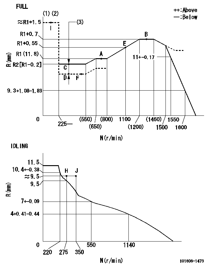
N:Pump speed
R:Rack position (mm)
(1)Torque cam stamping: T1
(2)Tolerance for racks not indicated: +-0.05mm.
(3)Boost compensator stroke: BCL
----------
T1=M18 BCL=0.5+-0.1mm
----------
----------
T1=M18 BCL=0.5+-0.1mm
----------
Speed control lever angle

F:Full speed
I:Idle
(1)Use the hole at R = aa
(2)Stopper bolt set position 'H'
----------
aa=40mm
----------
a=18.5deg+-5deg b=42deg+-3deg
----------
aa=40mm
----------
a=18.5deg+-5deg b=42deg+-3deg
Stop lever angle

N:Engine manufacturer's normal use
S:Stop the pump.
(1)Confirm that speed = aa, rack position = bb and the stopper bolt is set at non-injection at the speed lever's full setting.
(2)After setting the stopper bolt with the speed lever in the idle position, confirm non-injection at speed cc. Rack position = dd.
(3)R = approximately ee (speed lever full, speed = ff)
(4)Free (at delivery)
----------
aa=1400r/min bb=7-0.5mm cc=275r/min dd=(7.5)mm ee=(16)mm ff=0r/min
----------
a=39.5deg+-5deg b=(28deg) c=17deg+-5deg
----------
aa=1400r/min bb=7-0.5mm cc=275r/min dd=(7.5)mm ee=(16)mm ff=0r/min
----------
a=39.5deg+-5deg b=(28deg) c=17deg+-5deg
0000001501 MICRO SWITCH
Adjustment of the micro-switch
Adjust the bolt to obtain the following lever position when the micro-switch is ON.
(1)Speed N1
(2)Rack position Ra
----------
N1=400r/min Ra=9.6+-0.1mm
----------
----------
N1=400r/min Ra=9.6+-0.1mm
----------
0000001601 LEVER
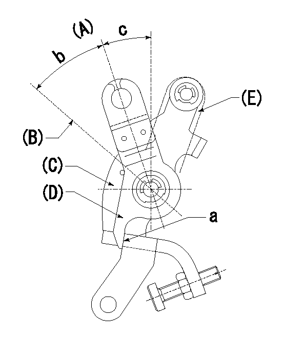
(A) Idle
(B) Full speed
(C) Base lever
(D) Accelerator lever
(E) Accelerator lever delivery position
1. Measure speed lever angle
(1)Measure the angle when the accelerator lever (D) contacted the base lever (C) at a.
----------
----------
b=42deg+-3deg c=18.5deg+-5deg
----------
----------
b=42deg+-3deg c=18.5deg+-5deg
Timing setting

(1)Pump vertical direction
(2)Position of timer's tooth at No 1 cylinder's beginning of injection
(3)B.T.D.C.: aa
(4)-
----------
aa=12deg
----------
a=(1deg)
----------
aa=12deg
----------
a=(1deg)
Information:
Illustration 7 g06347860
Injector male spade terminals
There are two options to build injector adapter harness for C3.3.If available, use the injector connector removed from C3.3 harness. Cut both 100 mm wires from the connector and attach bullet terminals that fit in the injector adapter harness C3.8 terminal from injector test kit.If no harness is available, build a harness with the following. Two female spade terminals for injector male spade terminal, two 16 gauge 100 mm wires, and two bullet terminals for injector adapter harness C3.8 terminal.
Illustration 8 g06345429
Injector adapter harness C2.4
Illustration 9 g06346223
Injector adapter harness C3.8
Illustration 10 g06346237
Injector male spade terminals
There are two options to build injector adapter harness for C2.4.If available, use the injector connector removed from C2.4 harness. Cut both 100 mm wires from the connector and attach bullet terminals that fit in the injector adapter harness C3.8 terminal from injector test kit.If no harness is available, build a harness with the following. Two female spade terminals for injector male spade terminal, two 16 gauge 100 mm wires, and two bullet terminals for injector adapter harness C3.8 terminal.Injector Test Set-up
Illustration 11 g06346391
Mounted nozzle test group
Find a suitable stable and surface to either mount or place the nozzle test group. Fill fuel container with #1 diesel and install high-pressure hose assembly. Use adaptors, if needed, based on nozzle tester. Tighten the fuel line adapter to (25 ft lbs). Install the fuel line adapter and tighten to (25 ft lbs) to allow connection to the injector.
Illustration 12 g06346423
Injector holder assembly
Take the injector test kit and remove all parts to assemble, as shown above. Take the injector holder and the clear fuel shield with screws from the kit and remove the screws using a 3mm alan wrench. Assemble the parts so the clear fuel shield with screws is on the bottom. While, the mounted injector holder is on top with the screws removed from before.
Illustration 13 g06346719
Fuel collector and injector holder
Place injector holder onto a fuel collector or another container to capture the injection spray.
Illustration 14 g06346839
Injector setup and harness connection
Install the injector that is needing to be tested into the opening at the top of injector holder. Attach the return fuel drain hose and run the drain hose to another fuel collector. Make the harness connection using the correct adapter for the C2.4, C3.3, and C3.8 engines. Connect the injector pulse tool and the injector adapter harness to the injector.
Illustration 15 g06346868
Complete setup of nozzle tester and injector test kit
Once injector test kit and nozzle test group are set up, connect fuel line adaptor on the high-pressure hose assembly to the injector, leave connection loose. Actuate the lever on the nozzle test group until fuel drips from connection allowing air to purge from setup. Tighten fuel line adaptor at injector to (25 ft lbs).Injector Test Procedure
Illustration 16 g06346881
Mounted nozzle test group (close-up)
Inspect the injector for any leaks. Using the lever on the nozzle tester group, build injection fuel pressure to (5000 psi). Turn the locking valve to insure there is no leakage back through the tester.
Let the nozzle test
Have questions with 101608-1473?
Group cross 101608-1473 ZEXEL
Mitsubishi
Mitsubishi
Mitsubishi
Mitsubishi
Mitsubishi
101608-1473
9 400 610 757
ME072742
INJECTION-PUMP ASSEMBLY
6D16T2
6D16T2