Information injection-pump assembly
ZEXEL
101608-1451
1016081451

Rating:
Service parts 101608-1451 INJECTION-PUMP ASSEMBLY:
1.
_

6.
COUPLING PLATE
7.
COUPLING PLATE
8.
_
9.
_
11.
Nozzle and Holder
ME078365
12.
Open Pre:MPa(Kqf/cm2)
17.7{180}

15.
NOZZLE SET
Cross reference number
ZEXEL
101608-1451
1016081451
Zexel num
Bosch num
Firm num
Name
101608-1451
INJECTION-PUMP ASSEMBLY
Calibration Data:
Adjustment conditions
Test oil
1404 Test oil ISO4113 or {SAEJ967d}
1404 Test oil ISO4113 or {SAEJ967d}
Test oil temperature
degC
40
40
45
Nozzle and nozzle holder
105780-8140
Bosch type code
EF8511/9A
Nozzle
105780-0000
Bosch type code
DN12SD12T
Nozzle holder
105780-2080
Bosch type code
EF8511/9
Opening pressure
MPa
17.2
Opening pressure
kgf/cm2
175
Injection pipe
Outer diameter - inner diameter - length (mm) mm 6-2-600
Outer diameter - inner diameter - length (mm) mm 6-2-600
Overflow valve
131424-5520
Overflow valve opening pressure
kPa
255
221
289
Overflow valve opening pressure
kgf/cm2
2.6
2.25
2.95
Tester oil delivery pressure
kPa
157
157
157
Tester oil delivery pressure
kgf/cm2
1.6
1.6
1.6
Direction of rotation (viewed from drive side)
Left L
Left L
Injection timing adjustment
Direction of rotation (viewed from drive side)
Left L
Left L
Injection order
1-5-3-6-
2-4
Pre-stroke
mm
4.5
4.45
4.55
Beginning of injection position
Governor side NO.1
Governor side NO.1
Difference between angles 1
Cal 1-5 deg. 60 59.5 60.5
Cal 1-5 deg. 60 59.5 60.5
Difference between angles 2
Cal 1-3 deg. 120 119.5 120.5
Cal 1-3 deg. 120 119.5 120.5
Difference between angles 3
Cal 1-6 deg. 180 179.5 180.5
Cal 1-6 deg. 180 179.5 180.5
Difference between angles 4
Cyl.1-2 deg. 240 239.5 240.5
Cyl.1-2 deg. 240 239.5 240.5
Difference between angles 5
Cal 1-4 deg. 300 299.5 300.5
Cal 1-4 deg. 300 299.5 300.5
Injection quantity adjustment
Adjusting point
A
Rack position
9.4
Pump speed
r/min
750
750
750
Average injection quantity
mm3/st.
118.5
115
122
Max. variation between cylinders
%
0
-3
3
Basic
*
Fixing the lever
*
Boost pressure
kPa
53.3
53.3
Boost pressure
mmHg
400
400
Injection quantity adjustment_02
Adjusting point
-
Rack position
6.4+-0.5
Pump speed
r/min
350
350
350
Average injection quantity
mm3/st.
10.6
9.1
12.1
Max. variation between cylinders
%
0
-15
15
Fixing the rack
*
Boost pressure
kPa
0
0
0
Boost pressure
mmHg
0
0
0
Remarks
Adjust only variation between cylinders; adjust governor according to governor specifications.
Adjust only variation between cylinders; adjust governor according to governor specifications.
Boost compensator adjustment
Pump speed
r/min
650
650
650
Rack position
R1-0.75
Boost pressure
kPa
28
25.3
30.7
Boost pressure
mmHg
210
190
230
Boost compensator adjustment_02
Pump speed
r/min
650
650
650
Rack position
R1(9.4)
Boost pressure
kPa
40
33.3
46.7
Boost pressure
mmHg
300
250
350
Timer adjustment
Pump speed
r/min
0
Advance angle
deg.
2
1.5
2.5
Timer adjustment_02
Pump speed
r/min
-
Advance angle
deg.
2
1.5
2.5
Remarks
Measure speed (beginning of operation).
Measure speed (beginning of operation).
Timer adjustment_03
Pump speed
r/min
550
Advance angle
deg.
0
0
0
Remarks
Finish
Finish
Test data Ex:
Governor adjustment
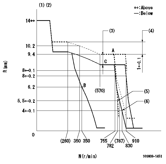
N:Pump speed
R:Rack position (mm)
(1)Target notch: K
(2)Tolerance for racks not indicated: +-0.05mm.
(3)Boost compensator stroke: BCL
(4)Rack difference between N = N1 and N = N2
(5)Main spring setting
(6)Set idle sub-spring
----------
K=15 BCL=0.75+-0.1 N1=750r/min N2=230r/min
----------
----------
K=15 BCL=0.75+-0.1 N1=750r/min N2=230r/min
----------
Speed control lever angle
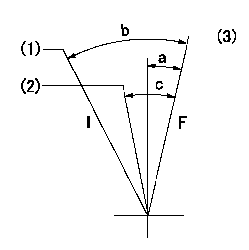
F:Full speed
I:Idle
(1)Stopper bolt setting
(2)Pump speed = aa
(3)Pump speed = bb
----------
aa=755r/min bb=910r/min
----------
a=(1deg)+-5deg b=(20deg)+-5deg c=(6deg)+-5deg
----------
aa=755r/min bb=910r/min
----------
a=(1deg)+-5deg b=(20deg)+-5deg c=(6deg)+-5deg
Stop lever angle
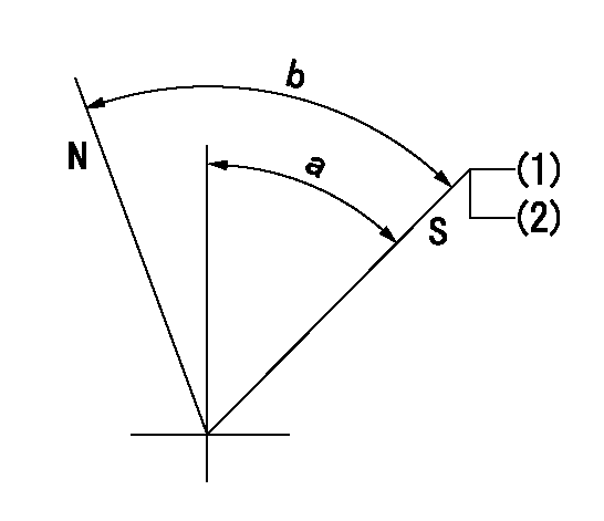
N:Pump normal
S:Stop the pump.
(1)Pump speed aa, rack position bb
(2)(Seal at delivery.)
----------
aa=0r/min bb=1-0.5mm
----------
a=35deg+-5deg b=(55deg)
----------
aa=0r/min bb=1-0.5mm
----------
a=35deg+-5deg b=(55deg)
Timing setting

(1)Pump vertical direction
(2)Position of coupling's tooth at No 1 cylinder's beginning of injection
(3)B.T.D.C.: aa
(4)-
----------
aa=10deg
----------
a=(1deg)
----------
aa=10deg
----------
a=(1deg)
Information:
Introduction
The problem that is identified below does not have a known permanent solution. Until a permanent solution is known, use the solution that is identified below.Note: The standard work for the laser mark has been updated.Problem
Illustration 1 g06273667During laser marking on these Reman 3400 HEUI injectors both Prime and Non-Prime injectors were marked with NP. This caused confusion with dealers and customers. The NP is thought to mean "Non-Prime" and the injectors are Prime injector part numbers. The prime injectors marked incorrectly with NP but were built and tested to the correct Prime part number and should be used in fuel systems for prime injectors. Dealers can remove the two letters if they decide the two letters cause too much confusion.Solution
Do not operate or work on this product unless you have read and understood the instruction and warnings in the relevant Operation and Maintenance Manuals and relevant service literature. Failure to follow the instructions or heed the warnings could result in injury or death. Proper care is your responsibility.
Illustration 2 g06273668
Prime HEUI injector
NP stands for "Non-Prime". Going forward only "Non-Prime" 3400 HEUI injectors will have the NP laser mark.
Have questions with 101608-1451?
Group cross 101608-1451 ZEXEL
Mitsubishi
Mitsubishi
101608-1451
INJECTION-PUMP ASSEMBLY