Information injection-pump assembly
BOSCH
F 019 Z20 008
f019z20008
ZEXEL
101608-1443
1016081443
MITSUBISHI
ME078428
me078428
Rating:
Service parts 101608-1443 INJECTION-PUMP ASSEMBLY:
1.
_

6.
COUPLING PLATE
7.
COUPLING PLATE
8.
_
9.
_
11.
Nozzle and Holder
12.
Open Pre:MPa(Kqf/cm2)
17.7(180)
15.
NOZZLE SET
Cross reference number
BOSCH
F 019 Z20 008
f019z20008
ZEXEL
101608-1443
1016081443
MITSUBISHI
ME078428
me078428
Zexel num
Bosch num
Firm num
Name
F 019 Z20 008
ME078428 MITSUBISHI
INJECTION-PUMP ASSEMBLY
6D16T * K 14BF INJECTION PUMP ASSY PE6AD PE
6D16T * K 14BF INJECTION PUMP ASSY PE6AD PE
Calibration Data:
Adjustment conditions
Test oil
1404 Test oil ISO4113 or {SAEJ967d}
1404 Test oil ISO4113 or {SAEJ967d}
Test oil temperature
degC
40
40
45
Nozzle and nozzle holder
105780-8140
Bosch type code
EF8511/9A
Nozzle
105780-0000
Bosch type code
DN12SD12T
Nozzle holder
105780-2080
Bosch type code
EF8511/9
Opening pressure
MPa
17.2
Opening pressure
kgf/cm2
175
Injection pipe
Outer diameter - inner diameter - length (mm) mm 6-2-600
Outer diameter - inner diameter - length (mm) mm 6-2-600
Overflow valve
131424-5520
Overflow valve opening pressure
kPa
255
221
289
Overflow valve opening pressure
kgf/cm2
2.6
2.25
2.95
Tester oil delivery pressure
kPa
157
157
157
Tester oil delivery pressure
kgf/cm2
1.6
1.6
1.6
Direction of rotation (viewed from drive side)
Left L
Left L
Injection timing adjustment
Direction of rotation (viewed from drive side)
Left L
Left L
Injection order
1-5-3-6-
2-4
Pre-stroke
mm
4.5
4.45
4.55
Beginning of injection position
Governor side NO.1
Governor side NO.1
Difference between angles 1
Cal 1-5 deg. 60 59.5 60.5
Cal 1-5 deg. 60 59.5 60.5
Difference between angles 2
Cal 1-3 deg. 120 119.5 120.5
Cal 1-3 deg. 120 119.5 120.5
Difference between angles 3
Cal 1-6 deg. 180 179.5 180.5
Cal 1-6 deg. 180 179.5 180.5
Difference between angles 4
Cyl.1-2 deg. 240 239.5 240.5
Cyl.1-2 deg. 240 239.5 240.5
Difference between angles 5
Cal 1-4 deg. 300 299.5 300.5
Cal 1-4 deg. 300 299.5 300.5
Injection quantity adjustment
Adjusting point
A
Rack position
10.6
Pump speed
r/min
1400
1400
1400
Average injection quantity
mm3/st.
106
105
107
Max. variation between cylinders
%
0
-2.5
2.5
Basic
*
Fixing the lever
*
Boost pressure
kPa
44
44
Boost pressure
mmHg
330
330
Injection quantity adjustment_02
Adjusting point
C
Rack position
8+-0.5
Pump speed
r/min
350
350
350
Average injection quantity
mm3/st.
8
6.5
9.5
Max. variation between cylinders
%
0
-15
15
Fixing the rack
*
Boost pressure
kPa
0
0
0
Boost pressure
mmHg
0
0
0
Boost compensator adjustment
Pump speed
r/min
650
650
650
Rack position
R1-0.9
Boost pressure
kPa
20
17.3
22.7
Boost pressure
mmHg
150
130
170
Boost compensator adjustment_02
Pump speed
r/min
650
650
650
Rack position
R1(10.6)
Boost pressure
kPa
30.7
24
37.4
Boost pressure
mmHg
230
180
280
Timer adjustment
Pump speed
r/min
0
Advance angle
deg.
1.5
1
2
Timer adjustment_02
Pump speed
r/min
-
Advance angle
deg.
1.5
1
2
Remarks
Measure speed (beginning of operation).
Measure speed (beginning of operation).
Timer adjustment_03
Pump speed
r/min
600
Advance angle
deg.
0
0
0
Remarks
Finish
Finish
Test data Ex:
Governor adjustment
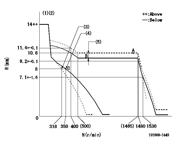
N:Pump speed
R:Rack position (mm)
(1)Notch fixed: K
(2)Tolerance for racks not indicated: +-0.05mm.
(3)Main spring setting
(4)Set idle sub-spring
(5)Boost compensator stroke: BCL
----------
K=13 BCL=0.9+-0.1mm
----------
----------
K=13 BCL=0.9+-0.1mm
----------
Speed control lever angle
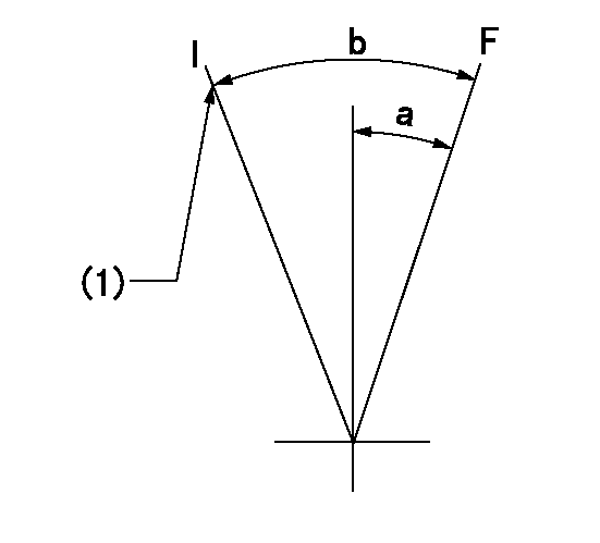
F:Full speed
I:Idle
(1)Stopper bolt setting
----------
----------
a=(20deg)+-5deg b=(30deg)+-5deg
----------
----------
a=(20deg)+-5deg b=(30deg)+-5deg
Stop lever angle
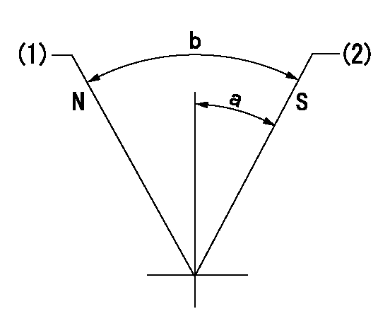
N:Pump normal
S:Stop the pump.
(1)Normal
(2)Pump speed aa and rack position bb (to be sealed at delivery)
----------
aa=0r/min bb=4-0.5mm
----------
a=28deg+-5deg b=(48deg)
----------
aa=0r/min bb=4-0.5mm
----------
a=28deg+-5deg b=(48deg)
Timing setting

(1)Pump vertical direction
(2)Position of timer's tooth at No 1 cylinder's beginning of injection
(3)B.T.D.C.: aa
(4)-
----------
aa=11deg
----------
a=(1deg)
----------
aa=11deg
----------
a=(1deg)
Information:
Introduction
The Environmental Protection Agency (EPA) has mandated that a DEF quality sensor must be installed on certain engines built after 2016. This new DEF quality sensor is integrated into the DEF header inside the DEF tank. The new style DEF header utilizes CAN C communication, so the wiring to the DEF header has been slightly modified on product going forward. However, the Dosing Control Unit (DCU) remains compatible to both setups with the latest engine software. ( 507-7605 Engine Software (24V DCU) or 507-7546 Engine Software (12V DCU)). As part of the DEF quality sensor implementation, a new configuration parameter setting is used on the engine Electronic Control Module (ECM) in Cat ET to identify whether a DEF quality sensor is"installed" or "not installed". Below are some different diagnostic codes for incompatible hardware and configuration setting as well as different service scenarios that may be encountered with this change and how to resolve any issues in these particular service scenarios. In addition to this Special Instruction, there is a video detailing these changes posted on Cat Channel 1.Diagnostic Codes When Parts/Settings Are Not Compatible
DEF quality header not installed but configuration set to "installed".
Table 1
J1939 Code and Description CDL Code and Description
1235-9
J1939 Network #3 : Abnormal Update Rate 5856-9
J1939 Network #3 : Abnormal Update Rate DEF quality header installed but configuration set to not installed.
Table 2
J1939 Code and Description CDL Code and Description
1761-3
Aftertreatment 1 Diesel Exhaust Fluid Tank Level : Voltage Above Normal 3130-3
Aftertreatment #1 SCR Catalyst Reagent Tank #1 Level Sensor : Voltage Above Normal
3031-3
Aftertreatment 1 Diesel Exhaust Fluid Tank Temperature : Voltage Above Normal 3134-3
Aftertreatment #1 SCR Catalyst Reagent Tank #1 Temperature Sensor : Voltage Above Normal DEF Quality Sensor Service Scenarios
Replacement Industrial Engine (2016 and earlier builds)
Replace with new engine (old engine no longer serviceable). Update to DEF quality sensor by installing a new DEF header, wiring harness, and DCU software and changing DEF quality sensor configuration status to "installed" in Cat ET.Replacement Machine Engine (2016 and Earlier Builds)
Replace with older service replacement Engine Arrangement Complete (EAC) engine (no other changes needed, confirm that DEF quality sensor configuration is set to "not installed" in CAT ET).
If dealer orders new EAC, update to DEF quality sensor is required (below scenario).Replacement Engine (2017and Future Builds)
Replace with latest EAC engine.Install DEF Quality Sensor on 2016 or Earlier Builds
Requires DCU software update, Pump, Electronic, and Tank Unit (PETU) wiring harness update, change DEF quality sensor configuration status to"installed".Replace DCU
No effect - new DCU hardware and software is compatible to both DEF headers.Replace Engine ECM
No effect when using ECM replacement file.
If engine ECM is replaced without the ECM replacement file, the DEF quality sensor configuration setting will default to "not installed" and may need to be updated if machine utilizes DEF quality sensor (requires Factory Passwords to change).Replace Wiring Harness
No effect - both new and old harness part numbers are available. Order same part number that is removed.