Information injection-pump assembly
BOSCH
F 019 Z20 007
f019z20007
ZEXEL
101608-1354
1016081354
MITSUBISHI
ME078410
me078410

Rating:
Service parts 101608-1354 INJECTION-PUMP ASSEMBLY:
1.
_

6.
COUPLING PLATE
7.
COUPLING PLATE
8.
_
9.
_
11.
Nozzle and Holder
ME078067
12.
Open Pre:MPa(Kqf/cm2)
17.7{180}
15.
NOZZLE SET
Cross reference number
BOSCH
F 019 Z20 007
f019z20007
ZEXEL
101608-1354
1016081354
MITSUBISHI
ME078410
me078410
Zexel num
Bosch num
Firm num
Name
F 019 Z20 007
ME078410 MITSUBISHI
INJECTION-PUMP ASSEMBLY
6D16T * K 14BF INJECTION PUMP ASSY PE6AD PE
6D16T * K 14BF INJECTION PUMP ASSY PE6AD PE
Calibration Data:
Adjustment conditions
Test oil
1404 Test oil ISO4113 or {SAEJ967d}
1404 Test oil ISO4113 or {SAEJ967d}
Test oil temperature
degC
40
40
45
Nozzle and nozzle holder
105780-8140
Bosch type code
EF8511/9A
Nozzle
105780-0000
Bosch type code
DN12SD12T
Nozzle holder
105780-2080
Bosch type code
EF8511/9
Opening pressure
MPa
17.2
Opening pressure
kgf/cm2
175
Injection pipe
Outer diameter - inner diameter - length (mm) mm 6-2-600
Outer diameter - inner diameter - length (mm) mm 6-2-600
Overflow valve
131424-5520
Overflow valve opening pressure
kPa
255
221
289
Overflow valve opening pressure
kgf/cm2
2.6
2.25
2.95
Tester oil delivery pressure
kPa
157
157
157
Tester oil delivery pressure
kgf/cm2
1.6
1.6
1.6
Direction of rotation (viewed from drive side)
Left L
Left L
Injection timing adjustment
Direction of rotation (viewed from drive side)
Left L
Left L
Injection order
1-5-3-6-
2-4
Pre-stroke
mm
4.5
4.45
4.55
Beginning of injection position
Governor side NO.1
Governor side NO.1
Difference between angles 1
Cal 1-5 deg. 60 59.5 60.5
Cal 1-5 deg. 60 59.5 60.5
Difference between angles 2
Cal 1-3 deg. 120 119.5 120.5
Cal 1-3 deg. 120 119.5 120.5
Difference between angles 3
Cal 1-6 deg. 180 179.5 180.5
Cal 1-6 deg. 180 179.5 180.5
Difference between angles 4
Cyl.1-2 deg. 240 239.5 240.5
Cyl.1-2 deg. 240 239.5 240.5
Difference between angles 5
Cal 1-4 deg. 300 299.5 300.5
Cal 1-4 deg. 300 299.5 300.5
Injection quantity adjustment
Adjusting point
A
Rack position
10.6
Pump speed
r/min
1400
1400
1400
Average injection quantity
mm3/st.
106
105
107
Max. variation between cylinders
%
0
-2.5
2.5
Basic
*
Fixing the lever
*
Boost pressure
kPa
44
44
Boost pressure
mmHg
330
330
Injection quantity adjustment_02
Adjusting point
C
Rack position
8+-0.5
Pump speed
r/min
350
350
350
Average injection quantity
mm3/st.
8
6.5
9.5
Max. variation between cylinders
%
0
-15
15
Fixing the rack
*
Boost pressure
kPa
0
0
0
Boost pressure
mmHg
0
0
0
Boost compensator adjustment
Pump speed
r/min
650
650
650
Rack position
R1-0.9
Boost pressure
kPa
20
17.3
22.7
Boost pressure
mmHg
150
130
170
Boost compensator adjustment_02
Pump speed
r/min
650
650
650
Rack position
R1(10.6)
Boost pressure
kPa
30.7
24
37.4
Boost pressure
mmHg
230
180
280
Timer adjustment
Pump speed
r/min
1150--
Advance angle
deg.
0
0
0
Load
4/4
Remarks
Beginning of advance.
Beginning of advance.
Timer adjustment_02
Pump speed
r/min
450
Advance angle
deg.
2
1.5
2.5
Load
0/4
Remarks
Start
Start
Timer adjustment_03
Pump speed
r/min
(550)
Advance angle
deg.
0
0
0
Load
0/4
Remarks
Measure the actual speed.
Measure the actual speed.
Timer adjustment_04
Pump speed
r/min
1100
Advance angle
deg.
0.5
Load
4/4
Timer adjustment_05
Pump speed
r/min
1400
Advance angle
deg.
2.5
2
3
Load
4/4
Remarks
Finish
Finish
Test data Ex:
Governor adjustment
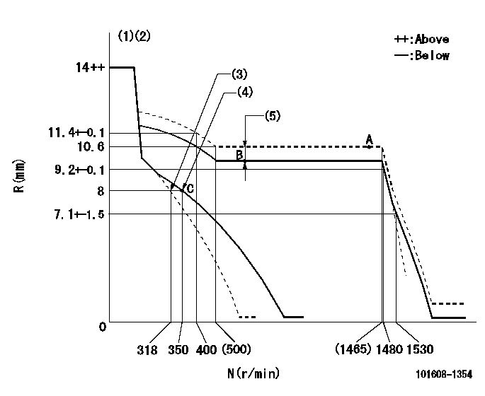
N:Pump speed
R:Rack position (mm)
(1)Notch fixed: K
(2)Tolerance for racks not indicated: +-0.05mm.
(3)Main spring setting
(4)Set idle sub-spring
(5)Boost compensator stroke: BCL
----------
K=13 BCL=0.9+-0.1mm
----------
----------
K=13 BCL=0.9+-0.1mm
----------
Speed control lever angle
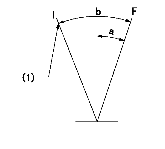
F:Full speed
I:Idle
(1)Stopper bolt setting
----------
----------
a=(20deg)+-5deg b=(30deg)+-5deg
----------
----------
a=(20deg)+-5deg b=(30deg)+-5deg
Stop lever angle
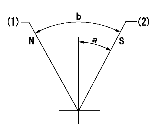
N:Pump normal
S:Stop the pump.
(1)Normal
(2)Pump speed aa and rack position bb (to be sealed at delivery)
----------
aa=0r/min bb=4-0.5mm
----------
a=28deg+-5deg b=(48deg)
----------
aa=0r/min bb=4-0.5mm
----------
a=28deg+-5deg b=(48deg)
Timing setting

(1)Pump vertical direction
(2)Position of timer's tooth at No 1 cylinder's beginning of injection
(3)B.T.D.C.: aa
(4)-
----------
aa=10deg
----------
a=(1deg)
----------
aa=10deg
----------
a=(1deg)
Information:
Introduction
The problem identified below does not have a permanent solution. Until a permanent solution is known, use the solution that is identified below.Problem
There have been instances of faults codes with the DEF Pump, which can lead to an engine derate condition. Affected part numbers for the DEF pumps are:
473-2749 Diesel Exhaust Fluid Pump Gp
473-2750 Diesel Exhaust Fluid Pump Gp
466-8285 Diesel Exhaust Fluid Pump Gp
466-8286 Diesel Exhaust Fluid Pump GpThe codes can be:
Table 1
Event Codes
J1939 Code CDL Code Description
4334-16 E930 (2) Aftertreatment #1 DEF #1 Pressure (absolute) : High - moderate severity (2)
4334-18 E931 (2) Aftertreatment #1 SCR Dosing Re-agent Absolute Pressure : Low - moderate severity (2)
4374-5 E3118 (6) Aftertreatment #1 Diesel Exhaust Fluid Pump Motor Speed : Current Below Normal
5392-31 E1370 (2) Aftertreatment Diesel Exhaust Fluid Dosing Unit Loss of Prime Caterpillar is investigating the root cause of these issues. To support the investigation, Caterpillar is requesting that the following steps are completed, documented, and recorded in SIMSi.Solution
Before starting any troubleshooting, download a Product Status Report (PSR) from the affected engine. Ensure that the PDF and the XML version of the PSR are downloaded, with the Histogram option selected in the Download List.Follow the appropriate troubleshooting steps for the displayed fault codes. Document the results of the troubleshooting tests in the relevant tables. Refer to Tables 2, 3, and 4.If Troubleshoot requests the Pump and Electronics Unit (PEU) to be replaced, conduct the following inspection before removal of the PEU.
Check the DEF for contamination, if the relevant troubleshooting procedure has not instructed you to do so. Refer to "System Operation Testing and Adjusting", Diesel Exhaust Fluid Quality - Test for the correct procedure.
Inspect the DEF tank cap, DEF header filter, DEF pump filter for any visible obstruction
Illustration 1 g06152768
(1) DEF line in
(2) DEF line out
(3) DEF line out let connection
(4) DEF line inlet connection
(5) Injector DEF line
Inspect and photograph both ends of the DEF fluid lines. If the ends of the lines are damaged or swollen, replace the DEF lines. Refer to "Disassembly and Assembly", Diesel Exhaust Fluid Lines - Remove and Install.At the end of the service take another PSR irrespective of outcome. Ensure that the PDF and the XML version of the PSR are downloaded, with the Histogram option selected in the Download List.If the troubleshooting steps have required a component to be changed, hold all replaced components for 30 days for a possible Parts Return Request (PRR). Make sure to include the closed work order paperwork.In every instance submit a SIMSi report, complete with TIB number M0079072, CPI number 359775 and submit through the CPI feedback tool within the SIMSi.
Detailed description of symptom experienced and under what conditions issue occurred
Product Status Report (PSR) before and after troubleshooting. Ensure that the PDF and the XML version of the PSR are downloaded, with the Histogram option selected in the Download List.
Completed Troubleshooting steps tables. Refer to Tables 2, 3, and 4.
Details of DEF tank cap, DEF header filter, DEF pump filter, visual inspection
Photos of DEF fluid lines
Details