Information injection-pump assembly
BOSCH
9 400 615 780
9400615780
ZEXEL
101608-1152
1016081152
MITSUBISHI
ME075640
me075640
Rating:
Service parts 101608-1152 INJECTION-PUMP ASSEMBLY:
1.
_
6.
COUPLING PLATE
7.
COUPLING PLATE
8.
_
9.
_
11.
Nozzle and Holder
ME075788
12.
Open Pre:MPa(Kqf/cm2)
15.7{160}/21.6{220}
14.
NOZZLE
Cross reference number
BOSCH
9 400 615 780
9400615780
ZEXEL
101608-1152
1016081152
MITSUBISHI
ME075640
me075640
Zexel num
Bosch num
Firm num
Name
101608-1152
9 400 615 780
ME075640 MITSUBISHI
INJECTION-PUMP ASSEMBLY
6D16 K
6D16 K
Calibration Data:
Adjustment conditions
Test oil
1404 Test oil ISO4113 or {SAEJ967d}
1404 Test oil ISO4113 or {SAEJ967d}
Test oil temperature
degC
40
40
45
Nozzle and nozzle holder
105780-8140
Bosch type code
EF8511/9A
Nozzle
105780-0000
Bosch type code
DN12SD12T
Nozzle holder
105780-2080
Bosch type code
EF8511/9
Opening pressure
MPa
17.2
Opening pressure
kgf/cm2
175
Injection pipe
Outer diameter - inner diameter - length (mm) mm 6-2-600
Outer diameter - inner diameter - length (mm) mm 6-2-600
Overflow valve
131424-8420
Overflow valve opening pressure
kPa
255
221
289
Overflow valve opening pressure
kgf/cm2
2.6
2.25
2.95
Tester oil delivery pressure
kPa
157
157
157
Tester oil delivery pressure
kgf/cm2
1.6
1.6
1.6
Direction of rotation (viewed from drive side)
Left L
Left L
Injection timing adjustment
Direction of rotation (viewed from drive side)
Left L
Left L
Injection order
1-5-3-6-
2-4
Pre-stroke
mm
3.2
3.15
3.25
Beginning of injection position
Governor side NO.1
Governor side NO.1
Difference between angles 1
Cal 1-5 deg. 60 59.5 60.5
Cal 1-5 deg. 60 59.5 60.5
Difference between angles 2
Cal 1-3 deg. 120 119.5 120.5
Cal 1-3 deg. 120 119.5 120.5
Difference between angles 3
Cal 1-6 deg. 180 179.5 180.5
Cal 1-6 deg. 180 179.5 180.5
Difference between angles 4
Cyl.1-2 deg. 240 239.5 240.5
Cyl.1-2 deg. 240 239.5 240.5
Difference between angles 5
Cal 1-4 deg. 300 299.5 300.5
Cal 1-4 deg. 300 299.5 300.5
Injection quantity adjustment
Adjusting point
-
Rack position
11.7
Pump speed
r/min
850
850
850
Each cylinder's injection qty
mm3/st.
78
75.7
80.3
Basic
*
Fixing the rack
*
Standard for adjustment of the maximum variation between cylinders
*
Injection quantity adjustment_02
Adjusting point
Z
Rack position
10+-0.5
Pump speed
r/min
480
480
480
Each cylinder's injection qty
mm3/st.
21.8
18.5
25.1
Fixing the rack
*
Standard for adjustment of the maximum variation between cylinders
*
Injection quantity adjustment_03
Adjusting point
A
Rack position
R1(11.7)
Pump speed
r/min
850
850
850
Average injection quantity
mm3/st.
78
77
79
Basic
*
Fixing the lever
*
Injection quantity adjustment_04
Adjusting point
B
Rack position
R1+0.25
Pump speed
r/min
1450
1450
1450
Average injection quantity
mm3/st.
82.5
78.5
86.5
Fixing the lever
*
Injection quantity adjustment_05
Adjusting point
C
Rack position
R1-0.55
Pump speed
r/min
500
500
500
Average injection quantity
mm3/st.
51.5
47.5
55.5
Fixing the lever
*
Injection quantity adjustment_06
Adjusting point
I
Rack position
-
Pump speed
r/min
100
100
100
Average injection quantity
mm3/st.
115
115
135
Fixing the lever
*
Rack limit
*
Timer adjustment
Pump speed
r/min
950--
Advance angle
deg.
0
0
0
Remarks
Start
Start
Timer adjustment_02
Pump speed
r/min
900
Advance angle
deg.
0.5
Timer adjustment_03
Pump speed
r/min
-
Advance angle
deg.
1
0.5
1.5
Remarks
Measure the actual speed.
Measure the actual speed.
Timer adjustment_04
Pump speed
r/min
1200
Advance angle
deg.
1
0.5
1.5
Timer adjustment_05
Pump speed
r/min
1450
Advance angle
deg.
7
6.5
7.5
Remarks
Finish
Finish
Test data Ex:
Governor adjustment
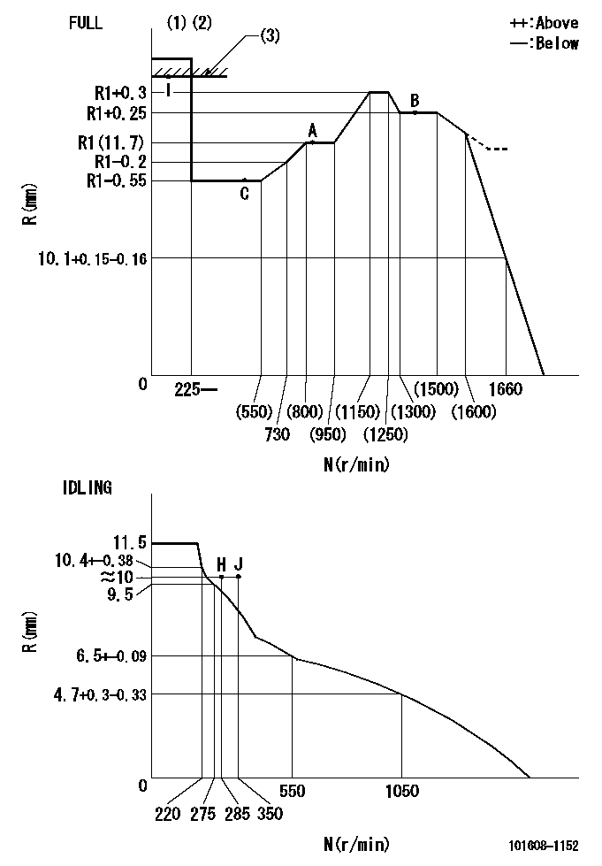
N:Pump speed
R:Rack position (mm)
(1)Torque cam stamping: T1
(2)Tolerance for racks not indicated: +-0.05mm.
(3)RACK LIMIT
----------
T1=M12
----------
----------
T1=M12
----------
Speed control lever angle
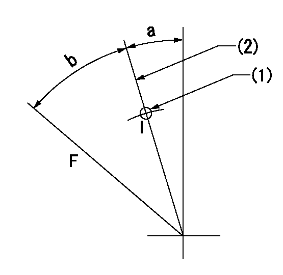
F:Full speed
I:Idle
(1)Use the hole at R = aa
(2)Stopper bolt set position 'H'
----------
aa=40mm
----------
a=21deg+-5deg b=38deg+-3deg
----------
aa=40mm
----------
a=21deg+-5deg b=38deg+-3deg
Stop lever angle
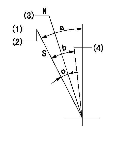
N:Engine manufacturer's normal use
S:Stop the pump.
(1)Set the stopper bolt at pump speed = aa and rack position = bb (non-injection rack position). Confirm non-injection.
(2)After setting the stopper bolt, confirm non-injection at speed cc. Rack position = dd (non-injection rack position).
(3)Rack position = approximately ee (speed lever full, speed = ff).
(4)Free (at delivery)
----------
aa=1450r/min bb=7.2-0.5mm cc=275r/min dd=(8.8)mm ee=15mm ff=0r/min
----------
a=36.5deg+-5deg b=(25deg) c=13deg+-5deg
----------
aa=1450r/min bb=7.2-0.5mm cc=275r/min dd=(8.8)mm ee=15mm ff=0r/min
----------
a=36.5deg+-5deg b=(25deg) c=13deg+-5deg
0000001501 LEVER
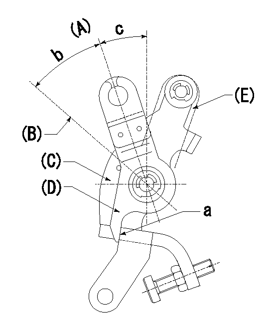
(A) Idle
(B) Full speed
(C) Base lever
(D) Accelerator lever
(E) Accelerator lever delivery position
1. Measure speed lever angle
(1)Measure the angle when the accelerator lever (D) contacted the base lever (C) at a.
----------
----------
b=38deg+-3deg c=21deg+-5deg
----------
----------
b=38deg+-3deg c=21deg+-5deg
Timing setting

(1)Pump vertical direction
(2)Position of timer's tooth at No 1 cylinder's beginning of injection
(3)B.T.D.C.: aa
(4)-
----------
aa=7deg
----------
a=(4deg)
----------
aa=7deg
----------
a=(4deg)
Information:
Caterpillar does not warrant the quality or performance of non-Cat fluids.
How Fuel and Oil Affects Cat DPF Performance
For the maximum performance in filtration and regeneration efficiency, operating the Cat DPF with ultra-low sulfur diesel fuel (ULSD-S15), of less than 15 ppm sulfur by weight is recommended. ULSD fuel must meet the S-15 fuels designation in the latest edition of ASTM D975 and/or conform to Cat Fuel Specification. Using ULSD, regeneration for engines certified to Tier II and lower regulations will occur when the duty cycle is above 300° C (572° F) for at least 30 percent of the operating time. For Tier III and greater engines, consult Cat for operating requirements.Operating the Cat DPF on diesel engines using fuel with sulfur content greater than 50 ppm will increase the regeneration temperature requirements significantly of approximately 50-90°C (90-135°F). If the exhaust temperature meets these requirements, continuous regeneration still can take place. If the normal operation of the Cat DPF is on ULSD but the engine is accidentally fueled with high sulfur fuel the regeneration temperature requirements will increase accordingly. With added sulfur, the normal duty cycle of the engine may cause the filter to plug with particulate matter PM. This condition will cause the backpressure to increase beyond the engine manufacturer limits. This condition could damage the filter and/or the engine.When the fuel sulfur level is once again below 50 ppm, ULSD operating conditions will return. High sulfur fuel will not damage the catalyst coating or the ceramic filter. High sulfur fuel will change the regeneration requirements as stated above.Biodiesel fuel may be used up to the B20 blend level (20 percent biodiesel and 80 percent appropriate ULSD fuel) IF the final B20 blend conforms to ASTM D7467 and API gravity 30-45. The neat biodiesel blend stock should conform to ASTM 6751. Cat diesel engine oils (CAT DEO) have been developed and tested in order to provide the full performance and service life that has been designed and built into Cat engines. Catt oils are currently used to fill Cat Diesel Engines at the factory. These oils are offered by Cat dealers for continued use when the engine oil is changed. Consult your Cat dealer for more information on these oils.Cat DEO-ULSTM(Ultra Low Sulfur) Oil exceeds the performance requirements of API category CJ-4 oil and is recommended due to a low ash specification. Engine oil that meets or exceeds the specifications in the Cat ECF-3 or API CJ4 categories may be used in these applications. Oil burned during the combustion process accounts for almost all of the DPF ash accumulation (because of oil additives). The use of recommended low ash oil results in lower ash accumulation in the filter. Failure to use the recommended grade of oil may results in more frequent ash removal service intervals.Note: Cat DEO and Cat DEO-ULS multigrade oils are the preferred oils for use in this Cat Diesel Engine.
Table 1
Commercial Lubricants Cat Lubricants Viscosity Grade
Diesel Engine Oil-Ultra Low Sulfur (API
Have questions with 101608-1152?
Group cross 101608-1152 ZEXEL
Mitsubishi
Mitsubishi
Mitsubishi
101608-1152
9 400 615 780
ME075640
INJECTION-PUMP ASSEMBLY
6D16
6D16