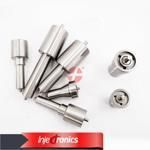
Information injection-pump assembly
BOSCH
9 400 610 747
9400610747
ZEXEL
101608-1064
1016081064
MITSUBISHI
ME075803
me075803
Rating:
Service parts 101608-1064 INJECTION-PUMP ASSEMBLY:
1.
_
6.
COUPLING PLATE
7.
COUPLING PLATE
8.
_
9.
_
11.
Nozzle and Holder
ME075761
12.
Open Pre:MPa(Kqf/cm2)
15.7{160}/21.6{220}
14.
NOZZLE
Include in #1:
101608-1064
as INJECTION-PUMP ASSEMBLY
Include in #2:
104746-5530
as _
Cross reference number
BOSCH
9 400 610 747
9400610747
ZEXEL
101608-1064
1016081064
MITSUBISHI
ME075803
me075803
Zexel num
Bosch num
Firm num
Name
9 400 610 747
ME075803 MITSUBISHI
INJECTION-PUMP ASSEMBLY
6D17-2 K 14BF INJECTION PUMP ASSY PE6AD PE
6D17-2 K 14BF INJECTION PUMP ASSY PE6AD PE
Calibration Data:
Adjustment conditions
Test oil
1404 Test oil ISO4113 or {SAEJ967d}
1404 Test oil ISO4113 or {SAEJ967d}
Test oil temperature
degC
40
40
45
Nozzle and nozzle holder
105780-8140
Bosch type code
EF8511/9A
Nozzle
105780-0000
Bosch type code
DN12SD12T
Nozzle holder
105780-2080
Bosch type code
EF8511/9
Opening pressure
MPa
17.2
Opening pressure
kgf/cm2
175
Injection pipe
Outer diameter - inner diameter - length (mm) mm 6-2-600
Outer diameter - inner diameter - length (mm) mm 6-2-600
Overflow valve
131424-8420
Overflow valve opening pressure
kPa
255
221
289
Overflow valve opening pressure
kgf/cm2
2.6
2.25
2.95
Tester oil delivery pressure
kPa
157
157
157
Tester oil delivery pressure
kgf/cm2
1.6
1.6
1.6
Direction of rotation (viewed from drive side)
Left L
Left L
Injection timing adjustment
Direction of rotation (viewed from drive side)
Left L
Left L
Injection order
1-5-3-6-
2-4
Pre-stroke
mm
3.2
3.15
3.25
Beginning of injection position
Governor side NO.1
Governor side NO.1
Difference between angles 1
Cal 1-5 deg. 60 59.5 60.5
Cal 1-5 deg. 60 59.5 60.5
Difference between angles 2
Cal 1-3 deg. 120 119.5 120.5
Cal 1-3 deg. 120 119.5 120.5
Difference between angles 3
Cal 1-6 deg. 180 179.5 180.5
Cal 1-6 deg. 180 179.5 180.5
Difference between angles 4
Cyl.1-2 deg. 240 239.5 240.5
Cyl.1-2 deg. 240 239.5 240.5
Difference between angles 5
Cal 1-4 deg. 300 299.5 300.5
Cal 1-4 deg. 300 299.5 300.5
Injection quantity adjustment
Adjusting point
-
Rack position
11.9
Pump speed
r/min
850
850
850
Each cylinder's injection qty
mm3/st.
81.5
79.1
83.9
Basic
*
Fixing the rack
*
Standard for adjustment of the maximum variation between cylinders
*
Injection quantity adjustment_02
Adjusting point
Z
Rack position
9.5+-0.5
Pump speed
r/min
600
600
600
Each cylinder's injection qty
mm3/st.
10.8
9.2
12.4
Fixing the rack
*
Standard for adjustment of the maximum variation between cylinders
*
Injection quantity adjustment_03
Adjusting point
A
Rack position
R1(11.9)
Pump speed
r/min
850
850
850
Average injection quantity
mm3/st.
81.5
80.5
82.5
Basic
*
Fixing the lever
*
Injection quantity adjustment_04
Adjusting point
B
Rack position
(R1+0.35
)
Pump speed
r/min
1450
1450
1450
Average injection quantity
mm3/st.
88
84
92
Fixing the lever
*
Injection quantity adjustment_05
Adjusting point
C
Rack position
R1-0.5
Pump speed
r/min
500
500
500
Average injection quantity
mm3/st.
59.5
55.5
63.5
Fixing the lever
*
Injection quantity adjustment_06
Adjusting point
I
Rack position
-
Pump speed
r/min
100
100
100
Average injection quantity
mm3/st.
95
85
105
Fixing the lever
*
Rack limit
*
Timer adjustment
Pump speed
r/min
1150--
Advance angle
deg.
0
0
0
Remarks
Start
Start
Timer adjustment_02
Pump speed
r/min
1100
Advance angle
deg.
0.5
Timer adjustment_03
Pump speed
r/min
1450
Advance angle
deg.
5
4.5
5.5
Remarks
Finish
Finish
Test data Ex:
Governor adjustment
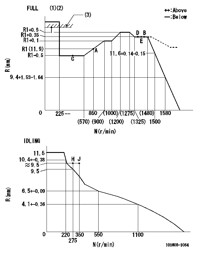
N:Pump speed
R:Rack position (mm)
(1)Torque cam stamping: T1
(2)Tolerance for racks not indicated: +-0.05mm.
(3)RACK LIMIT
----------
T1=L01
----------
----------
T1=L01
----------
Speed control lever angle
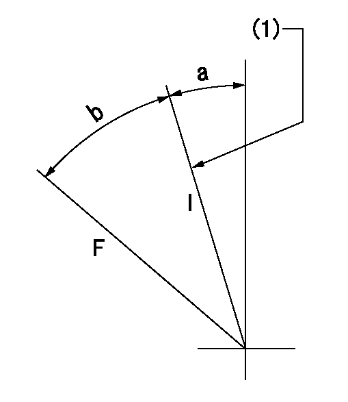
F:Full speed
I:Idle
(1)Stopper bolt setting
----------
----------
a=18.5deg+-5deg b=39deg+-3deg
----------
----------
a=18.5deg+-5deg b=39deg+-3deg
Stop lever angle
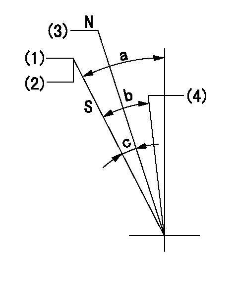
N:Engine manufacturer's normal use
S:Stop the pump.
(1)Set the stopper bolt at speed = aa and rack position = bb and confirm non-injection.
(2)After setting the stopper bolt, confirm non-injection at speed = cc and rack position = dd.
(3)R = approximately ee (speed lever full, speed = ff)
(4)Free (at delivery)
----------
aa=1450r/min bb=7.2-0.5mm cc=275r/min dd=(8.8)mm ee=15mm ff=0r/min
----------
a=36.5deg+-5deg b=(25deg) c=13deg+-5deg
----------
aa=1450r/min bb=7.2-0.5mm cc=275r/min dd=(8.8)mm ee=15mm ff=0r/min
----------
a=36.5deg+-5deg b=(25deg) c=13deg+-5deg
0000001501 LEVER
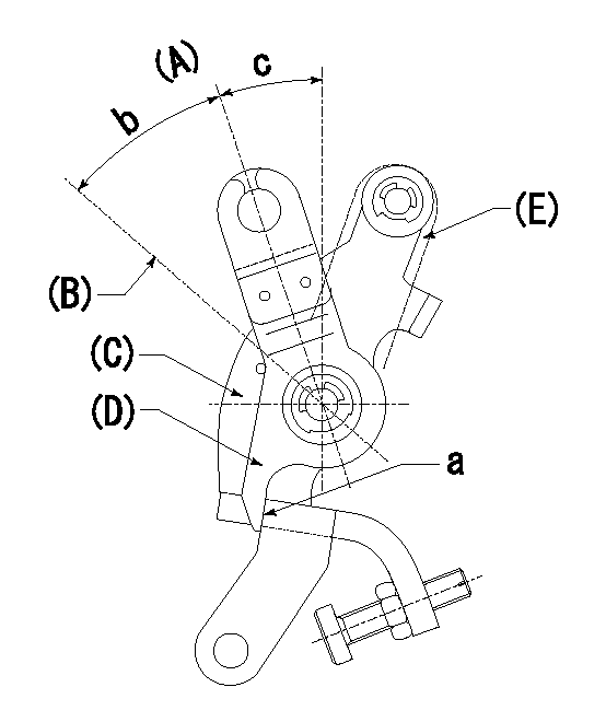
(A) Idle
(B) Full speed
(C) Base lever
(D) Accelerator lever
(E) Accelerator lever delivery position
1. Measure speed lever angle
(1)Measure the angle when the accelerator lever (D) contacted the base lever (C) at a.
----------
----------
b=39deg+-3deg c=18.5deg+-5deg
----------
----------
b=39deg+-3deg c=18.5deg+-5deg
Timing setting

(1)Pump vertical direction
(2)Position of timer's tooth at No 1 cylinder's beginning of injection
(3)B.T.D.C.: aa
(4)-
----------
aa=7deg
----------
a=(4deg)
----------
aa=7deg
----------
a=(4deg)
Information:
This Special Instruction details the Diesel Particulate Filter (DPF) maintenance on C2.4, C3.3B, and C3.8 machine engines.Do not perform any procedure in this Special Instruction until you have read the information and you understand the information.Reference
Reference: Special Instructions , REHS7788, "Cleaning the Diesel Particulate Filter (DPF) on C2.4, C3.3B, and C3.8 Engines."Reference: Troubleshooting , "Diesel Particulate Filter Active Regeneration Occurrence is Excessive".Reference: Troubleshooting , "Oil Contains Fuel".Reference: Disassembly and Assembly , "Diesel Particulate Filter- Remove and Install".Safety
Do not operate or work on this product unless you have read and understood the instruction and warnings in the relevant Operation and Maintenance Manuals and relevant service literature. Failure to follow the instructions or heed the warnings could result in injury or death. Proper care is your responsibility.
Failure to follow all safety guidelines prescribed in this document and by governing authorities and regulatory agencies may result in severe injury or death of personnel or machine damage.
When removing a major component or attachment, ensure that it is properly blocked or secured before removing mounting hardware. An assembly that is disconnected without proper blocking may shift or fall, resulting in serious injury or death of personnel or machine damage.
Personal injury or death can result from improper maintenance procedures. To avoid injury or death, follow the procedures exactly as stated below.
Personal injury can result from improper handling of chemicals.Make sure you use all the necessary protective equipment required to do the job.Make sure that you read and understand all directions and hazards described on the labels and material safety data sheet of any chemical that is used.Observe all safety precautions recommended by the chemical manufacturer for handling, storage, and disposal of chemicals.
Maintenance Procedure
There are three options for servicing the Diesel Particulate Filter (DPF).
Diesel Particulate Filter (DPF) can be cleaned by the Cat® dealer.
Replaced with a certified clean Diesel Particulate Filter (DPF) from Cat® Reman.
New Diesel Particulate Filter (DPF) installed.Note: The lowest cost option is the Diesel Particulate Filter (DPF) is cleaned by the Cat® dealer.
Refer to Special Instructions , REHS7788 for cleaning procedures.This document has the acceptable reuse guidelines such as max number of cracked or missing end caps and minimum remaining ash pin depth as measured by a pin gauge.Note: The C3.8 tier 4 final (EU stage 3B) currently does not have a certified clean Diesel Particulate Filter (DPF) available from Cat® Reman.
DPF cleaning is recommended to do at 3000 hrs as part of preventive maintenance, which ensures planned downtime. If the dealer and customer choose to not do this pro-actively at 3000 hrs, then Caterpillar is not responsible for any subsequent damage to the engine or emission components as a result.
If preventive maintenance is not done pro-actively, one of the following will occur which may indicate the Diesel Particulate Filter (DPF) is full or near full:
523602-0 High Frequency Regeneration code occurs.
Fuel Dilution is flagged in the SOS oil sample.
523602-0 High Frequency Regeneration indicated that active regenerations (in-cylinder dosing) occurred within 30 minutes of the prior and this occurred three times in a
