Information injection-pump assembly
BOSCH
F 01G 09U 05Y
f01g09u05y
ZEXEL
101607-9824
1016079824
NISSAN-DIESEL
16714Z5605
16714z5605

Rating:
Include in #1:
101402-8130
as _
Cross reference number
BOSCH
F 01G 09U 05Y
f01g09u05y
ZEXEL
101607-9824
1016079824
NISSAN-DIESEL
16714Z5605
16714z5605
Zexel num
Bosch num
Firm num
Name
101607-9824
F 01G 09U 05Y
16714Z5605 NISSAN-DIESEL
INJECTION-PUMP ASSEMBLY
FE6E * K
FE6E * K
Calibration Data:
Adjustment conditions
Test oil
1404 Test oil ISO4113 or {SAEJ967d}
1404 Test oil ISO4113 or {SAEJ967d}
Test oil temperature
degC
40
40
45
Nozzle and nozzle holder
105780-8260
Bosch type code
9 430 610 133
Nozzle
105780-0120
Bosch type code
1 688 901 990
Nozzle holder
105780-2190
Opening pressure
MPa
18
Opening pressure
kgf/cm2
184
Injection pipe
Outer diameter - inner diameter - length (mm) mm 6-2-600
Outer diameter - inner diameter - length (mm) mm 6-2-600
Overflow valve
131425-0420
Overflow valve opening pressure
kPa
157
123
191
Overflow valve opening pressure
kgf/cm2
1.6
1.25
1.95
Tester oil delivery pressure
kPa
255
255
255
Tester oil delivery pressure
kgf/cm2
2.6
2.6
2.6
Direction of rotation (viewed from drive side)
Right R
Right R
Injection timing adjustment
Direction of rotation (viewed from drive side)
Right R
Right R
Injection order
1-4-2-6-
3-5
Pre-stroke
mm
3.7
3.65
3.75
Beginning of injection position
Drive side NO.1
Drive side NO.1
Difference between angles 1
Cal 1-4 deg. 60 59.5 60.5
Cal 1-4 deg. 60 59.5 60.5
Difference between angles 2
Cyl.1-2 deg. 120 119.5 120.5
Cyl.1-2 deg. 120 119.5 120.5
Difference between angles 3
Cal 1-6 deg. 180 179.5 180.5
Cal 1-6 deg. 180 179.5 180.5
Difference between angles 4
Cal 1-3 deg. 240 239.5 240.5
Cal 1-3 deg. 240 239.5 240.5
Difference between angles 5
Cal 1-5 deg. 300 299.5 300.5
Cal 1-5 deg. 300 299.5 300.5
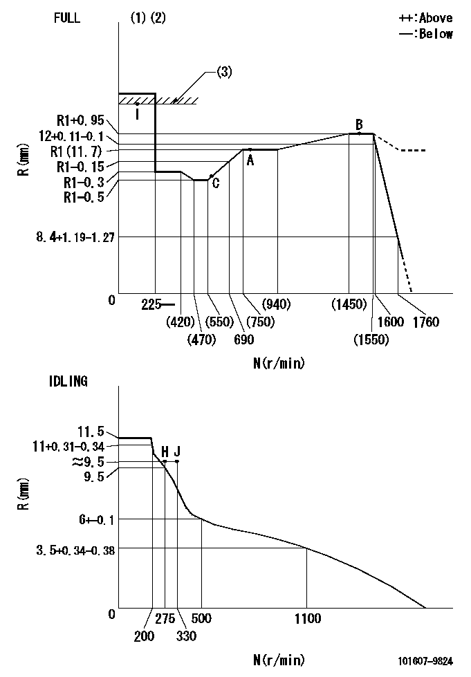
Injection quantity adjustment
Adjusting point
-
Rack position
11.7
Pump speed
r/min
800
800
800
Average injection quantity
mm3/st.
92
90.4
93.6
Max. variation between cylinders
%
0
-3.5
3.5
Basic
*
Fixing the rack
*
Standard for adjustment of the maximum variation between cylinders
*
Injection quantity adjustment_02
Adjusting point
Z
Rack position
9.5+-0.5
Pump speed
r/min
265
265
265
Average injection quantity
mm3/st.
9
7.2
10.8
Max. variation between cylinders
%
0
-10
10
Fixing the rack
*
Standard for adjustment of the maximum variation between cylinders
*
Injection quantity adjustment_03
Adjusting point
A
Rack position
R1(11.7)
Pump speed
r/min
800
800
800
Average injection quantity
mm3/st.
92
91
93
Basic
*
Fixing the lever
*
Injection quantity adjustment_04
Adjusting point
B
Rack position
R1+0.95
Pump speed
r/min
1500
1500
1500
Average injection quantity
mm3/st.
97.5
93.5
101.5
Fixing the lever
*
Injection quantity adjustment_05
Adjusting point
C
Rack position
(R1-0.35
)
Pump speed
r/min
600
600
600
Average injection quantity
mm3/st.
86.5
82.5
90.5
Fixing the lever
*
Injection quantity adjustment_06
Adjusting point
I
Rack position
-
Pump speed
r/min
100
100
100
Average injection quantity
mm3/st.
105
105
115
Fixing the lever
*
Rack limit
*
Timer adjustment
Pump speed
r/min
(900)
Advance angle
deg.
0
0
0
Remarks
Start
Start
Timer adjustment_02
Pump speed
r/min
1080
Advance angle
deg.
2
1.5
2.5
Timer adjustment_03
Pump speed
r/min
1225
Advance angle
deg.
2
1.5
2.5
Timer adjustment_04
Pump speed
r/min
1425
Advance angle
deg.
6
5.5
6.5
Remarks
Finish
Finish
Test data Ex:
Governor adjustment
N:Pump speed
R:Rack position (mm)
(1)Torque cam stamping: T1
(2)Tolerance for racks not indicated: +-0.05mm.
(3)RACK LIMIT
----------
T1=L78
----------
----------
T1=L78
----------
Speed control lever angle

F:Full speed
I:Idle
(1)Use the hole at R = aa
(2)Stopper bolt set position 'H'
----------
aa=39mm
----------
a=20deg+-5deg b=42deg+-3deg
----------
aa=39mm
----------
a=20deg+-5deg b=42deg+-3deg
Stop lever angle
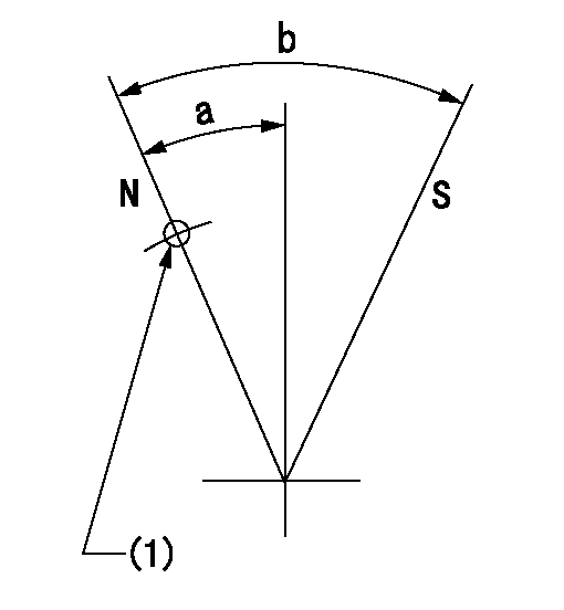
N:Pump normal
S:Stop the pump.
(1)Use the pin at R = aa
----------
aa=42mm
----------
a=25deg+-5deg b=40deg+-5deg
----------
aa=42mm
----------
a=25deg+-5deg b=40deg+-5deg
0000001501 LEVER
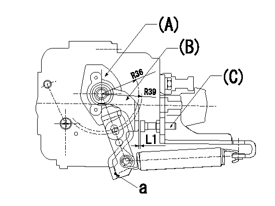
(a) Speed lever
(B) Accelerator lever
(C) Accelerator lever stopper bolt
1. Accelerator lever setting method
With the speed lever in the idling position, back off the accelerator lever stopper bolt L1 from where it contacts point a. (Back off 1+0.5 turns and set.)
----------
L1=1+0.5 mm
----------
----------
L1=1+0.5 mm
----------
Timing setting

(1)Pump vertical direction
(2)Position of timer's threaded hole at No 1 cylinder's beginning of injection
(3)-
(4)-
----------
----------
a=(60deg)
----------
----------
a=(60deg)
Information:
Introduction
The problem that is identified below does not have a known permanent solution. Until a permanent solution is known, use the solution that is identified below.Problem
Illustration 1 g06201989Certain Cat® Reman 3500 electronic fuel injectors may be marked with incorrect trim codes. Cat Reman 3500 electronic fuel injectors marked with trim code "2755" manufactured between 09 January 2017and 18 April 2017may be affected.The trim code is not correct for every injector. Refer to Illustration 1 for trim code identification. Serial numbers of suspect injectors range from (S/N: 1825569-1880788).Solution
Caterpillar is aware of this problem, but a permanent repair has not been identified. As an interim action, follow the below procedure:
All Reman 3500 electronic fuel injectors marked with trim code "2755" manufactured between 09 January 2017and 18 April 2017are suspect. Refer to Illustration 1.Caterpillar has created a tool which will help to identify injectors labeled with the incorrect trim code. Use the link below to download the file.https://cat.box.com/s/4fwh9nz0lwguh8vomifxj2rapqjc27e9
Enter the injector Serial Number in the spreadsheet downloaded. The spreadsheet will indicate whether the code is ok to use as is, or the spreadsheet will return the correct trim code.
Illustration 2 g06203882
If the trim code is incorrect, the injector must be relabeled. Use an engraving tool to cross out the original (incorrect) trim code (2755) and write the correct trim code on the injector tappet. Refer to Illustration 2.
Illustration 3 g06202000
Mark the box for each part that has been either reworked or verified to be correct, to identify that the parts are good to use. Refer to Illustration 3.
For individual injector replacements in engines, update the ECM with the correct trim code. Injectors must be marked with the correct trim code.Note: Do not return affected parts to Caterpillar. Use the procedure listed above to remark and use existing stock.Note: The issue has been resolved in the factory. Factory stock has been reworked and shipped. Parts in the distribution system are being sorted for return & rework.Note: Injector boxes have been marked with a large green dot to indicate that the injector has been sorted and marked correctly, or the trim code is correct.
Have questions with 101607-9824?
Group cross 101607-9824 ZEXEL
Nissan-Diesel
Nissan-Diesel
101607-9824
F 01G 09U 05Y
16714Z5605
INJECTION-PUMP ASSEMBLY
FE6E
FE6E