Information injection-pump assembly
ZEXEL
101607-9820
1016079820
NISSAN-DIESEL
16713Z6567
16713z6567

Rating:
Cross reference number
ZEXEL
101607-9820
1016079820
NISSAN-DIESEL
16713Z6567
16713z6567
Zexel num
Bosch num
Firm num
Name
Calibration Data:
Adjustment conditions
Test oil
1404 Test oil ISO4113 or {SAEJ967d}
1404 Test oil ISO4113 or {SAEJ967d}
Test oil temperature
degC
40
40
45
Nozzle and nozzle holder
105780-8260
Bosch type code
9 430 610 133
Nozzle
105780-0120
Bosch type code
1 688 901 990
Nozzle holder
105780-2190
Opening pressure
MPa
18
Opening pressure
kgf/cm2
184
Injection pipe
Outer diameter - inner diameter - length (mm) mm 6-2-600
Outer diameter - inner diameter - length (mm) mm 6-2-600
Overflow valve
131425-0420
Overflow valve opening pressure
kPa
157
123
191
Overflow valve opening pressure
kgf/cm2
1.6
1.25
1.95
Tester oil delivery pressure
kPa
255
255
255
Tester oil delivery pressure
kgf/cm2
2.6
2.6
2.6
Direction of rotation (viewed from drive side)
Right R
Right R
Injection timing adjustment
Direction of rotation (viewed from drive side)
Right R
Right R
Injection order
1-4-2-6-
3-5
Pre-stroke
mm
3.7
3.65
3.75
Beginning of injection position
Drive side NO.1
Drive side NO.1
Difference between angles 1
Cal 1-4 deg. 60 59.5 60.5
Cal 1-4 deg. 60 59.5 60.5
Difference between angles 2
Cyl.1-2 deg. 120 119.5 120.5
Cyl.1-2 deg. 120 119.5 120.5
Difference between angles 3
Cal 1-6 deg. 180 179.5 180.5
Cal 1-6 deg. 180 179.5 180.5
Difference between angles 4
Cal 1-3 deg. 240 239.5 240.5
Cal 1-3 deg. 240 239.5 240.5
Difference between angles 5
Cal 1-5 deg. 300 299.5 300.5
Cal 1-5 deg. 300 299.5 300.5
Injection quantity adjustment
Adjusting point
-
Rack position
11.7
Pump speed
r/min
800
800
800
Average injection quantity
mm3/st.
92
90.4
93.6
Max. variation between cylinders
%
0
-3.5
3.5
Basic
*
Fixing the rack
*
Standard for adjustment of the maximum variation between cylinders
*
Injection quantity adjustment_02
Adjusting point
Z
Rack position
9.5+-0.5
Pump speed
r/min
265
265
265
Average injection quantity
mm3/st.
9
7.2
10.8
Max. variation between cylinders
%
0
-10
10
Fixing the rack
*
Standard for adjustment of the maximum variation between cylinders
*
Injection quantity adjustment_03
Adjusting point
A
Rack position
R1(11.7)
Pump speed
r/min
800
800
800
Average injection quantity
mm3/st.
92
91
93
Basic
*
Fixing the lever
*
Injection quantity adjustment_04
Adjusting point
B
Rack position
R1+0.95
Pump speed
r/min
1500
1500
1500
Average injection quantity
mm3/st.
97.5
93.5
101.5
Fixing the lever
*
Injection quantity adjustment_05
Adjusting point
C
Rack position
(R1-0.35
)
Pump speed
r/min
600
600
600
Average injection quantity
mm3/st.
86.5
82.5
90.5
Fixing the lever
*
Injection quantity adjustment_06
Adjusting point
I
Rack position
-
Pump speed
r/min
100
100
100
Average injection quantity
mm3/st.
105
105
115
Fixing the lever
*
Rack limit
*
Timer adjustment
Pump speed
r/min
(900)
Advance angle
deg.
0
0
0
Remarks
Start
Start
Timer adjustment_02
Pump speed
r/min
1080
Advance angle
deg.
2
1.5
2.5
Timer adjustment_03
Pump speed
r/min
1225
Advance angle
deg.
2
1.5
2.5
Timer adjustment_04
Pump speed
r/min
1425
Advance angle
deg.
6
5.5
6.5
Remarks
Finish
Finish
Test data Ex:
Governor adjustment
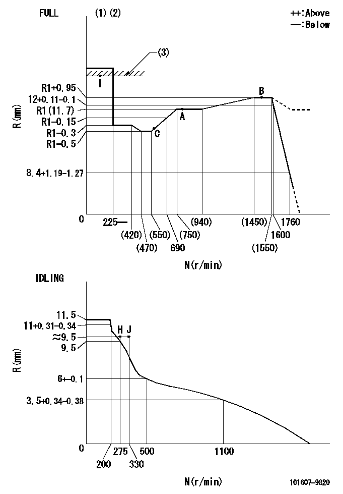
N:Pump speed
R:Rack position (mm)
(1)Torque cam stamping: T1
(2)Tolerance for racks not indicated: +-0.05mm.
(3)RACK LIMIT
----------
T1=L78
----------
----------
T1=L78
----------
Speed control lever angle

F:Full speed
I:Idle
(1)Use the hole at R = aa
(2)Stopper bolt set position 'H'
----------
aa=39mm
----------
a=20deg+-5deg b=42deg+-3deg
----------
aa=39mm
----------
a=20deg+-5deg b=42deg+-3deg
Stop lever angle
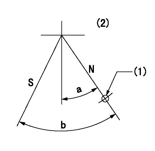
N:Pump normal
S:Stop the pump.
(1)Use the hole at R = aa
(2)No return spring
----------
aa=28mm
----------
a=20deg+-5deg b=40deg+-5deg
----------
aa=28mm
----------
a=20deg+-5deg b=40deg+-5deg
0000001501 LEVER
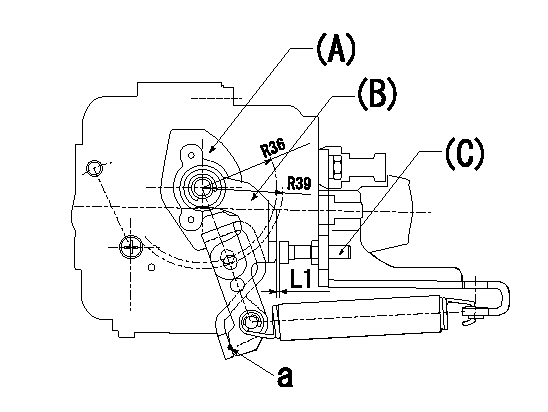
(a) Speed lever
(B) Accelerator lever
(C) Accelerator lever stopper bolt
1. Accelerator lever setting method
With the speed lever in the idling position, back off the accelerator lever stopper bolt L1 from where it contacts point a. (Back off 1+0.5 turns and set.)
----------
L1=1+0.5 mm
----------
----------
L1=1+0.5 mm
----------
Timing setting

(1)Pump vertical direction
(2)Position of timer's threaded hole at No 1 cylinder's beginning of injection
(3)-
(4)-
----------
----------
a=(60deg)
----------
----------
a=(60deg)
Information:
Use of Cat Diesel Fuel System Cleaner or Cat Diesel Fuel System Conditioner does not lessen the responsibility of the engine owner and/or responsibility of the fuel supplier to follow all industry standard maintenance practices for fuel storage and for fuel handling. Refer to the “General Fuel Information” article in this Special Publication for additional information. Additionally, use of Cat Diesel Fuel System Cleaner or Cat Diesel Fuel System Conditioner does NOT lessen the responsibility of the owner of the engine to use appropriate diesel fuel. Refer to the “Fuel Specifications” section in this Special Publication (Maintenance Section) for guidance.
Cat strongly recommends the use of Cat Diesel Fuel Conditioner with biodiesel and biodiesel blends. Cat Diesel Fuel Conditioner is suitable for use with biodiesel/biodiesel blends that meet Cat biodiesel recommendations and requirements. Not all fuel additives are suitable for use with biodiesel/biodiesel blends. Read and follow all applicable label usage instructions. Also, refer to this Special Publication, "Distillate Diesel Fuel" article and also refer to the “Biodiesel” article, which includes Cat biodiesel recommendations and requirements.Cat Diesel Fuel Conditioner has proven to be compatible with existing and U.S. EPA 2007 on-highway certified diesel engine emission control catalysts and particulate filters.Note: When used as directed, Cat Diesel Fuel Conditioner will not raise fuel sulfur levels measurably in the final fuel/additive blend. In the U.S. the current formulation of Cat Diesel Fuel Conditioner must be blended in at the recommended treat-rate at the fuel supplier/distributor level for use in on-highway or other applications where use of ULSD fuel is mandated (15 ppm or less fuel sulfur). Follow all applicable national, regional, and local laws, mandates, and regulations concerning the use of diesel fuel conditioners/additives.
When used as directed Cat Diesel Fuel Conditioner will not raise fuel sulfur levels measurably in the final fuel/additive blend. Follow all applicable national, regional, and local laws, mandates, and regulations concerning the use of diesel fuel conditioners/additives.
Cat Diesel Fuel System Cleaner
Note: Cat Diesel Fuel System Cleaner, part number 343-6210, is the only fuel system cleaner available to the end user that is tested and approved by Cat for use in Cat diesel engines.Cat Diesel Fuel System Cleaner is a proven high performance detergent product designed for cleaning deposits that form in the fuel system. Deposits in the fuel system reduce system performance and can increase fuel consumption. Cat Diesel Fuel System Cleaner addresses the deposits formed due to the use of degraded diesel fuel, poor quality diesel fuel, and diesel fuel containing high quantities of high molecular weight compounds. Cat Diesel Fuel System Cleaner addresses deposits formed due to the use of biodiesel, biodiesel blends, and biodiesel that does not meet the appropriate quality specifications. Continued use of Cat Diesel Fuel System Cleaner is proven to inhibit the growth of new deposits.Cat Diesel Fuel System Cleaner can be added directly to diesel fuel, biodiesel, or biodiesel blends. Cat Diesel Fuel System Cleaner is a United States Environmental Protection Agency registered fuel additive that can be used with