Information injection-pump assembly
BOSCH
9 400 615 763
9400615763
ZEXEL
101607-9801
1016079801
NISSAN-DIESEL
16714Z6017
16714z6017

Rating:
Include in #2:
104746-5400
as _
Cross reference number
BOSCH
9 400 615 763
9400615763
ZEXEL
101607-9801
1016079801
NISSAN-DIESEL
16714Z6017
16714z6017
Zexel num
Bosch num
Firm num
Name
101607-9801
9 400 615 763
16714Z6017 NISSAN-DIESEL
INJECTION-PUMP ASSEMBLY
MD92 * K
MD92 * K
Calibration Data:
Adjustment conditions
Test oil
1404 Test oil ISO4113 or {SAEJ967d}
1404 Test oil ISO4113 or {SAEJ967d}
Test oil temperature
degC
40
40
45
Nozzle and nozzle holder
105780-8260
Bosch type code
9 430 610 133
Nozzle
105780-0120
Bosch type code
1 688 901 990
Nozzle holder
105780-2190
Opening pressure
MPa
18
Opening pressure
kgf/cm2
184
Injection pipe
Outer diameter - inner diameter - length (mm) mm 6-2-600
Outer diameter - inner diameter - length (mm) mm 6-2-600
Overflow valve
131424-8921
Overflow valve opening pressure
kPa
157
123
191
Overflow valve opening pressure
kgf/cm2
1.6
1.25
1.95
Tester oil delivery pressure
kPa
255
255
255
Tester oil delivery pressure
kgf/cm2
2.6
2.6
2.6
Direction of rotation (viewed from drive side)
Left L
Left L
Injection timing adjustment
Direction of rotation (viewed from drive side)
Left L
Left L
Injection order
1-4-2-6-
3-5
Pre-stroke
mm
3.7
3.65
3.75
Beginning of injection position
Governor side NO.1
Governor side NO.1
Difference between angles 1
Cal 1-4 deg. 60 59.5 60.5
Cal 1-4 deg. 60 59.5 60.5
Difference between angles 2
Cyl.1-2 deg. 120 119.5 120.5
Cyl.1-2 deg. 120 119.5 120.5
Difference between angles 3
Cal 1-6 deg. 180 179.5 180.5
Cal 1-6 deg. 180 179.5 180.5
Difference between angles 4
Cal 1-3 deg. 240 239.5 240.5
Cal 1-3 deg. 240 239.5 240.5
Difference between angles 5
Cal 1-5 deg. 300 299.5 300.5
Cal 1-5 deg. 300 299.5 300.5
Injection quantity adjustment
Adjusting point
-
Rack position
11.8
Pump speed
r/min
800
800
800
Average injection quantity
mm3/st.
95
93.4
96.6
Max. variation between cylinders
%
0
-3.5
3.5
Basic
*
Fixing the rack
*
Standard for adjustment of the maximum variation between cylinders
*
Injection quantity adjustment_02
Adjusting point
Z
Rack position
9.5+-0.5
Pump speed
r/min
280
280
280
Average injection quantity
mm3/st.
12
11
13
Max. variation between cylinders
%
0
-10
10
Fixing the rack
*
Standard for adjustment of the maximum variation between cylinders
*
Injection quantity adjustment_03
Adjusting point
A
Rack position
R1(11.8)
Pump speed
r/min
800
800
800
Average injection quantity
mm3/st.
95
94
96
Basic
*
Fixing the lever
*
Injection quantity adjustment_04
Adjusting point
B
Rack position
R1+0.9
Pump speed
r/min
1450
1450
1450
Average injection quantity
mm3/st.
100.5
96.5
104.5
Fixing the lever
*
Injection quantity adjustment_05
Adjusting point
I
Rack position
-
Pump speed
r/min
100
100
100
Average injection quantity
mm3/st.
125
125
135
Fixing the lever
*
Rack limit
*
Timer adjustment
Pump speed
r/min
970--
Advance angle
deg.
0
0
0
Remarks
Start
Start
Timer adjustment_02
Pump speed
r/min
920
Advance angle
deg.
0.5
Timer adjustment_03
Pump speed
r/min
(1000)
Advance angle
deg.
1.5
1
2
Timer adjustment_04
Pump speed
r/min
1160
Advance angle
deg.
1.5
1
2
Timer adjustment_05
Pump speed
r/min
1450
Advance angle
deg.
7
6.5
7.5
Remarks
Finish
Finish
Test data Ex:
Governor adjustment
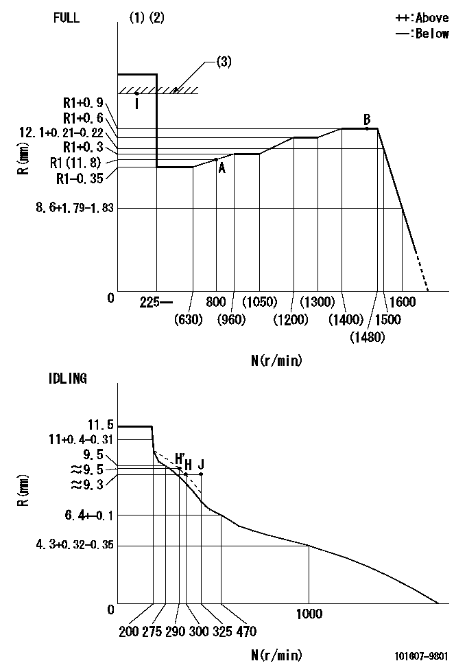
N:Pump speed
R:Rack position (mm)
(1)Torque cam stamping: T1
(2)Tolerance for racks not indicated: +-0.05mm.
(3)RACK LIMIT
----------
T1=M00
----------
----------
T1=M00
----------
Speed control lever angle

F:Full speed
I:Idle
(1)Use the hole at R = aa
(2)Stopper bolt set position 'H'
----------
aa=36mm
----------
a=6.5deg+-5deg b=(42.5deg)+-3deg
----------
aa=36mm
----------
a=6.5deg+-5deg b=(42.5deg)+-3deg
Stop lever angle
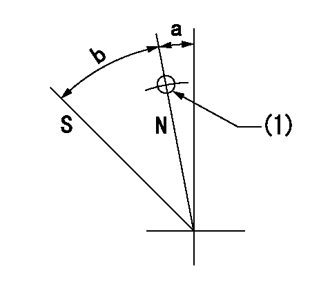
N:Pump normal
S:Stop the pump.
(1)Use the pin at R = aa
----------
aa=42mm
----------
a=5deg+-5deg b=40deg+-5deg
----------
aa=42mm
----------
a=5deg+-5deg b=40deg+-5deg
Timing setting

(1)Pump vertical direction
(2)Position of timer's threaded hole at No 1 cylinder's beginning of injection
(3)-
(4)-
----------
----------
a=(80deg)
----------
----------
a=(80deg)
Information:
Illustration 5 g01943178
Coil without debris
Illustration 6 g03351850
(2) Debris on the coil
Inspect the coil for debris.The debris will be visible in the form of metal shavings on the coil. Refer to Illustration. If the coil is covered in soot, use a clean magnet to locate the debris.Note: DO NOT use high-pressure fluid or other cleaning solvents. Debris may be lost during cleaning.
If debris is present and/or an injector is inoperable perform the remaining Steps that are in Special Instruction, REHS3819, "Procedure for Troubleshooting and Cleaning the Oil Rail System for the Hydraulic Electronic Unit Injector (HEUI)". Ensure that the system is flushed through six injector bores, two large and six small plugs.
Illustration 7 g03344174
Close-up view of cylinder head (3) 9S-8003 Plug (4) 214-7567 O-Ring Seal (5) 205-3079 Adapter , and sensor location (if needed)
Cylinder heads that were manufactured prior to January 2006 must relocate the HEUI pressure sensor. Refer to Illustration 7 for the proper location for the HEUI pressure sensor.
Install plug (3) with seal (4) into the port.
Install sensor into the cylinder head at cylinder number 4.
Install sensor into the cylinder head at cylinder number 4, utilizing the following components: 205-3079 Adapter , 214-7567 O-Ring Seal and 214-7568 O-Ring Seal
Illustration 8 g03355201
(6) Fuel pump (7) Gear
Install fuel pump (6) .
Illustration 9 g03345875
(6) Fuel pump (8) Bolts
Position fuel pump (6) and install bolts (8) through the front housing.
Illustration 10 g03355149
View of 242-7032 Engine Oil Lines Gp (9) 6V-9850 Elbow (10) 228-7089 O-Ring Seal (11) 378-8430 Tube As (12) 8C-8988 Elbow
Illustration 11 g03355176
Proper tightening sequence for oil line fittings
Install elbow (9) with o-ring seal (10) onto the fuel pump. Do not tighten the fitting. Refer to Illustration 10
Install elbow (12) with o-ring seal (10) onto the cylinder head port. Do not tighten the fitting.
Install tube assembly (11).
Tighten the fittings to a torque of 45 N m (33 lb ft), that are shown in Illustration 11 using the proper torque sequence.
Illustration 12 g03345035
View of 388-2124 Unit Injection Hydraulic Pump and Mounting Gp (10) 228-7089 O-Ring Seal (13) 068-4174 Elbow (14) 238-5081 O-Ring Seal (15) 6V-8724 Elbow (16) 214-7568 O-Ring Seal (17) 6V-8636 Connector (18) 030-7950 Elbow (19) 238-5082 O-Ring Seal (20) 387-9500 Tube As (21) 387-7159 Tube As (22) 2R-6806 O-Ring Connector (23) 384-0678 or 20R-1636 Unit Injector Hydraulic Pump Gp (24) 9S-8004 Plug
Use the following Steps in order to install the fittings and plugs from the current pump to the new pump. Refer to Illustration 12 for the proper location of the fittings and plugs.
Install the fitting (10) with o-ring seal (16, 17) .
Install fitting (22) with o-ring seal (16) .
Install plug (24) with o-ring seal (16)
Install elbow (15) with o-ring seal (10, 16) onto the fuel pump.
Connect the harness assembly to the connector of the fuel pump.
Install elbow (13) with o-ring seal (14). Refer to Illustration 12
Have questions with 101607-9801?
Group cross 101607-9801 ZEXEL
Nissan-Diesel
101607-9801
9 400 615 763
16714Z6017
INJECTION-PUMP ASSEMBLY
MD92
MD92