Information injection-pump assembly
BOSCH
9 400 610 735
9400610735
ZEXEL
101607-9780
1016079780
NISSAN-DIESEL
16713Z6560
16713z6560

Rating:
Service parts 101607-9780 INJECTION-PUMP ASSEMBLY:
1.
_
7.
COUPLING PLATE
8.
_
9.
_
11.
Nozzle and Holder
16600-Z6004
12.
Open Pre:MPa(Kqf/cm2)
16.7{170}/22.6{230}
15.
NOZZLE SET
Include in #1:
101607-9780
as INJECTION-PUMP ASSEMBLY
Include in #2:
104746-5350
as _
Cross reference number
BOSCH
9 400 610 735
9400610735
ZEXEL
101607-9780
1016079780
NISSAN-DIESEL
16713Z6560
16713z6560
Zexel num
Bosch num
Firm num
Name
Calibration Data:
Adjustment conditions
Test oil
1404 Test oil ISO4113 or {SAEJ967d}
1404 Test oil ISO4113 or {SAEJ967d}
Test oil temperature
degC
40
40
45
Nozzle and nozzle holder
105780-8260
Bosch type code
9 430 610 133
Nozzle
105780-0120
Bosch type code
1 688 901 990
Nozzle holder
105780-2190
Opening pressure
MPa
18
Opening pressure
kgf/cm2
184
Injection pipe
Outer diameter - inner diameter - length (mm) mm 6-2-600
Outer diameter - inner diameter - length (mm) mm 6-2-600
Overflow valve
131424-8921
Overflow valve opening pressure
kPa
157
123
191
Overflow valve opening pressure
kgf/cm2
1.6
1.25
1.95
Tester oil delivery pressure
kPa
255
255
255
Tester oil delivery pressure
kgf/cm2
2.6
2.6
2.6
Direction of rotation (viewed from drive side)
Left L
Left L
Injection timing adjustment
Direction of rotation (viewed from drive side)
Left L
Left L
Injection order
1-4-2-6-
3-5
Pre-stroke
mm
3.7
3.65
3.75
Beginning of injection position
Governor side NO.1
Governor side NO.1
Difference between angles 1
Cal 1-4 deg. 60 59.5 60.5
Cal 1-4 deg. 60 59.5 60.5
Difference between angles 2
Cyl.1-2 deg. 120 119.5 120.5
Cyl.1-2 deg. 120 119.5 120.5
Difference between angles 3
Cal 1-6 deg. 180 179.5 180.5
Cal 1-6 deg. 180 179.5 180.5
Difference between angles 4
Cal 1-3 deg. 240 239.5 240.5
Cal 1-3 deg. 240 239.5 240.5
Difference between angles 5
Cal 1-5 deg. 300 299.5 300.5
Cal 1-5 deg. 300 299.5 300.5
Injection quantity adjustment
Adjusting point
-
Rack position
11.8
Pump speed
r/min
800
800
800
Average injection quantity
mm3/st.
95
93.4
96.6
Max. variation between cylinders
%
0
-3.5
3.5
Basic
*
Fixing the rack
*
Standard for adjustment of the maximum variation between cylinders
*
Injection quantity adjustment_02
Adjusting point
Z
Rack position
9.5+-0.5
Pump speed
r/min
280
280
280
Average injection quantity
mm3/st.
12
11
13
Max. variation between cylinders
%
0
-10
10
Fixing the rack
*
Standard for adjustment of the maximum variation between cylinders
*
Injection quantity adjustment_03
Adjusting point
A
Rack position
R1(11.8)
Pump speed
r/min
800
800
800
Average injection quantity
mm3/st.
95
94
96
Basic
*
Fixing the lever
*
Injection quantity adjustment_04
Adjusting point
B
Rack position
R1+0.9
Pump speed
r/min
1450
1450
1450
Average injection quantity
mm3/st.
100.5
96.5
104.5
Fixing the lever
*
Injection quantity adjustment_05
Adjusting point
I
Rack position
-
Pump speed
r/min
100
100
100
Average injection quantity
mm3/st.
125
125
135
Fixing the lever
*
Rack limit
*
Timer adjustment
Pump speed
r/min
970--
Advance angle
deg.
0
0
0
Remarks
Start
Start
Timer adjustment_02
Pump speed
r/min
920
Advance angle
deg.
0.5
Timer adjustment_03
Pump speed
r/min
(1000)
Advance angle
deg.
1.5
1
2
Timer adjustment_04
Pump speed
r/min
1160
Advance angle
deg.
1.5
1
2
Timer adjustment_05
Pump speed
r/min
1450
Advance angle
deg.
7
6.5
7.5
Remarks
Finish
Finish
Test data Ex:
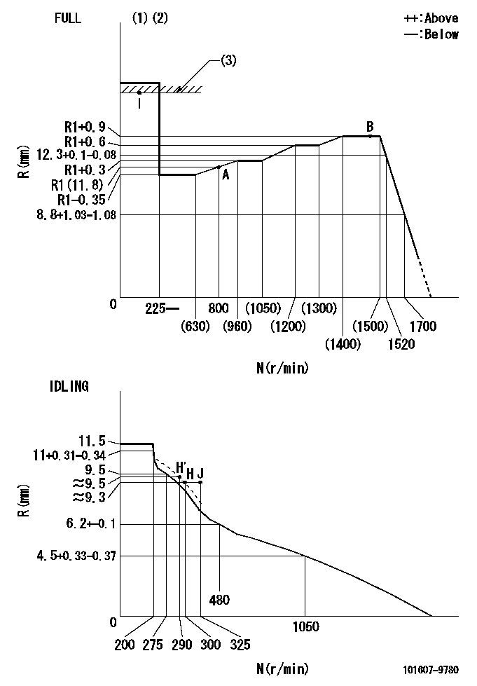
Governor adjustment

N:Pump speed
R:Rack position (mm)
(1)Torque cam stamping: T1
(2)Tolerance for racks not indicated: +-0.05mm.
(3)RACK LIMIT
----------
T1=L85
----------
----------
T1=L85
----------
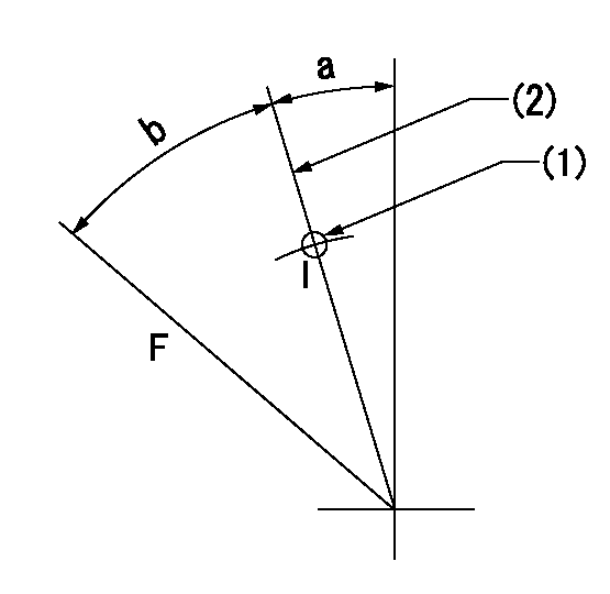
Speed control lever angle

F:Full speed
I:Idle
(1)Use the hole at R = aa
(2)Stopper bolt set position 'H'
----------
aa=38mm
----------
a=6.5deg+-5deg b=35deg+-3deg
----------
aa=38mm
----------
a=6.5deg+-5deg b=35deg+-3deg
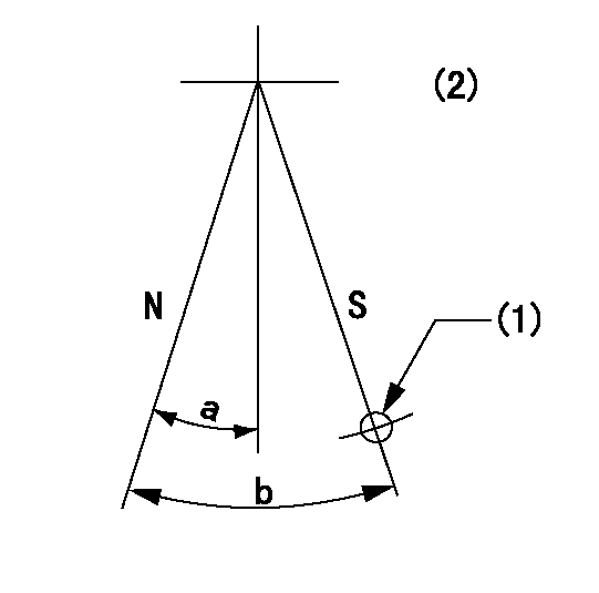
Stop lever angle

N:Pump normal
S:Stop the pump.
(1)Use the hole at R = aa
(2)No return spring
----------
aa=32mm
----------
a=10deg+-5deg b=40deg+-5deg
----------
aa=32mm
----------
a=10deg+-5deg b=40deg+-5deg
Timing setting

(1)Pump vertical direction
(2)Position of timer's threaded hole at No 1 cylinder's beginning of injection
(3)-
(4)-
----------
----------
a=(80deg)
----------
----------
a=(80deg)
Information:
Locations and Methods for Measuring the Pressures of the Low-Pressure Fuel System
Illustration 1 g03325145
Front View of a typical fuel inlet lines group (A) Fuel inlet port (B) Test port for the fuel supply pressure (C) Fuel transfer pump (D) Test port location for system pressureInlet Fuel Pressure to the Transfer Pump (set at rated speed and load)
Install a 6V-3965 Fitting into Port (B) using a 214-7568 O-Ring Seal Note: The inlet pressure to the fuel transfer pump can affect overall system pressure. All filters or water separators before the transfer pump must be new and clean prior to setting the system pressure at the fuel pressure regulator.
Connect the 6V-7830 Pressure Gauge to the fitting installed in the previous step.
Set the engine to rated speed and load. Record the fuel pressure, and refer to the specifications above.Primary and Secondary Fuel Filter Differential Pressure
Primary and secondary fuel filter differential pressures are determined by the pressures from both sides of the fuel filters. This measurement will monitor fuel filter cleanliness and determine when the fuel filters require changing. Filter replacement will vary depending on fuel quality. Fuel quality can change with each shipment of fuel so monitoring the filter differential is necessary to obtain maximum filter life.Too high of a differential can cause air bubbles in the fuel system and if not corrected will lead to poor performance and injector damage. After the measurements are taken, refer to the specification above for the maximum allowable differential pressure.Primary filters or water separators should be properly sized to meet the flow requirements of the engine or engines as well as fuel being returned to the tank. Reference Table 4 for the flow requirements.
Table 4
3600 Engine Fuel Flow
Engine Model Rated Speed (rpm) Fuel Flow to Engine Fuel Flow from Engine Fuel Heat Rejection
3606 1000
41.5 L/min (11 US gpm)
32.4 L/min (8.6 US gpm)
12.5 kW (712 Btu/min)
900
38 L/min (10 US gpm)
30.0 L/min (7.9 US gpm)
11.0 kW (626 Btu/min)
750
31.5 L/min (8.3 US gpm)
24.5 L/min (6.5 US gpm)
10.5 kW (598 Btu/min)
720
30 L/min (7.9 US gpm)
23.6 L/min (6.2 US gpm)
10.0 kW (567 Btu/min)
3608 1000
41.5 L/min (11 US gpm)
30.0 L/min (7.9 US gpm)
16.7 kW (951 Btu/min)
900
38 L/min (10 US gpm)
27.6 L/min (7.3 US gpm)
14.6 kW (831 Btu/min)
750
31.5 L/min (8.3 US gpm)
22.6 L/min (6.0 US gpm)
14.0 kW (797 Btu/min)
720
30 L/min (7.9 US gpm)
21.4 L/min (5.6 US gpm)
13.3 kW (757 Btu/min)
3612 1000
78.5 L/min (20.7 US gpm)
60.1 L/min (15.9 US gpm)
25.0 kW (1423 Btu/min)
900
72 L/min (19 US gpm)
55.4 L/min (14.6 US gpm)
22.0 kW (1252 Btu/min)
750
61.2 L/min (16.2 US gpm)
47.3