Information injection-pump assembly
ZEXEL
101607-9772
1016079772
NISSAN-DIESEL
16714Z5602
16714z5602
Rating:
Cross reference number
ZEXEL
101607-9772
1016079772
NISSAN-DIESEL
16714Z5602
16714z5602
Zexel num
Bosch num
Firm num
Name
101607-9772
16714Z5602 NISSAN-DIESEL
INJECTION-PUMP ASSEMBLY
FE6A * K
FE6A * K
Calibration Data:
Adjustment conditions
Test oil
1404 Test oil ISO4113 or {SAEJ967d}
1404 Test oil ISO4113 or {SAEJ967d}
Test oil temperature
degC
40
40
45
Nozzle and nozzle holder
105780-8140
Bosch type code
EF8511/9A
Nozzle
105780-0000
Bosch type code
DN12SD12T
Nozzle holder
105780-2080
Bosch type code
EF8511/9
Opening pressure
MPa
17.2
Opening pressure
kgf/cm2
175
Injection pipe
Outer diameter - inner diameter - length (mm) mm 6-2-600
Outer diameter - inner diameter - length (mm) mm 6-2-600
Overflow valve
134424-1520
Overflow valve opening pressure
kPa
162
147
177
Overflow valve opening pressure
kgf/cm2
1.65
1.5
1.8
Tester oil delivery pressure
kPa
157
157
157
Tester oil delivery pressure
kgf/cm2
1.6
1.6
1.6
Direction of rotation (viewed from drive side)
Right R
Right R
Injection timing adjustment
Direction of rotation (viewed from drive side)
Right R
Right R
Injection order
1-4-2-6-
3-5
Pre-stroke
mm
3.4
3.35
3.45
Beginning of injection position
Drive side NO.1
Drive side NO.1
Difference between angles 1
Cal 1-4 deg. 60 59.5 60.5
Cal 1-4 deg. 60 59.5 60.5
Difference between angles 2
Cyl.1-2 deg. 120 119.5 120.5
Cyl.1-2 deg. 120 119.5 120.5
Difference between angles 3
Cal 1-6 deg. 180 179.5 180.5
Cal 1-6 deg. 180 179.5 180.5
Difference between angles 4
Cal 1-3 deg. 240 239.5 240.5
Cal 1-3 deg. 240 239.5 240.5
Difference between angles 5
Cal 1-5 deg. 300 299.5 300.5
Cal 1-5 deg. 300 299.5 300.5
Injection quantity adjustment
Adjusting point
-
Rack position
12
Pump speed
r/min
800
800
800
Average injection quantity
mm3/st.
71
69.4
72.6
Max. variation between cylinders
%
0
-3.5
3.5
Basic
*
Fixing the rack
*
Standard for adjustment of the maximum variation between cylinders
*
Injection quantity adjustment_02
Adjusting point
H
Rack position
9.5+-0.5
Pump speed
r/min
275
275
275
Average injection quantity
mm3/st.
10
8.2
11.8
Max. variation between cylinders
%
0
-10
10
Fixing the rack
*
Standard for adjustment of the maximum variation between cylinders
*
Injection quantity adjustment_03
Adjusting point
A
Rack position
R1(12)
Pump speed
r/min
800
800
800
Average injection quantity
mm3/st.
71
70
72
Basic
*
Fixing the lever
*
Injection quantity adjustment_04
Adjusting point
B
Rack position
R1(12)
Pump speed
r/min
1500
1500
1500
Average injection quantity
mm3/st.
83
79
87
Fixing the lever
*
Injection quantity adjustment_05
Adjusting point
I
Rack position
-
Pump speed
r/min
100
100
100
Average injection quantity
mm3/st.
80
80
90
Fixing the lever
*
Rack limit
*
Timer adjustment
Pump speed
r/min
1200--
Advance angle
deg.
0
0
0
Remarks
Start
Start
Timer adjustment_02
Pump speed
r/min
1150
Advance angle
deg.
0.5
Timer adjustment_03
Pump speed
r/min
1500
Advance angle
deg.
6.5
6.2
6.8
Remarks
Finish
Finish
Test data Ex:
Governor adjustment
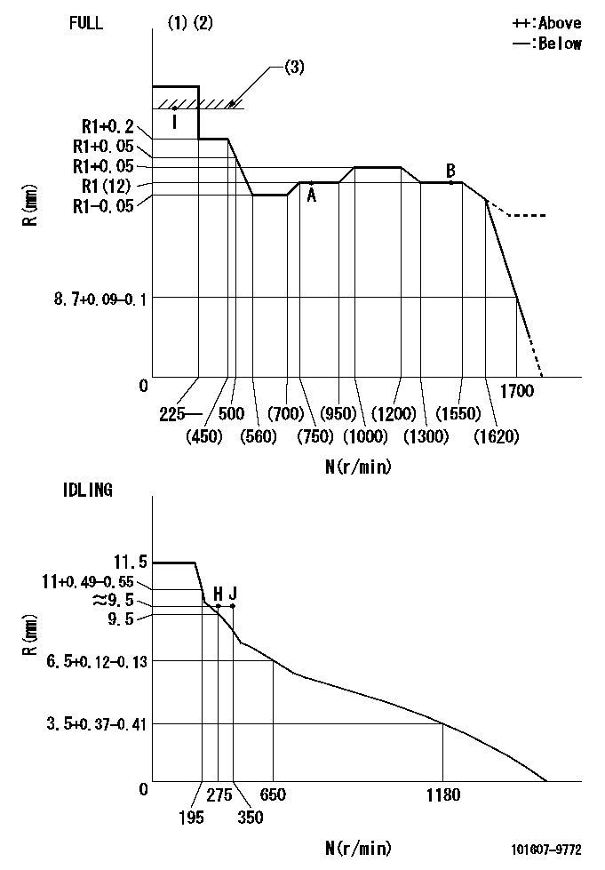
N:Pump speed
R:Rack position (mm)
(1)Torque cam stamping: T1
(2)Tolerance for racks not indicated: +-0.05mm.
(3)RACK LIMIT
----------
T1=L66
----------
----------
T1=L66
----------
Speed control lever angle

F:Full speed
I:Idle
(1)Use the hole at R = aa
(2)Stopper bolt set position 'H'
----------
aa=100mm
----------
a=26.5deg+-5deg b=(46deg)+-3deg
----------
aa=100mm
----------
a=26.5deg+-5deg b=(46deg)+-3deg
Stop lever angle
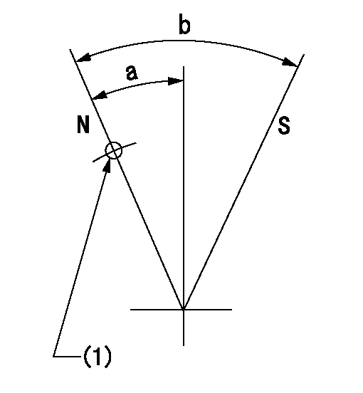
N:Pump normal
S:Stop the pump.
(1)Use the pin at R = aa
----------
aa=42mm
----------
a=25deg+-5deg b=40deg+-5deg
----------
aa=42mm
----------
a=25deg+-5deg b=40deg+-5deg
0000001501 RACK SENSOR
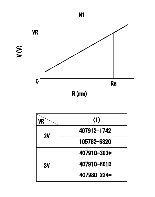
R:Rack position (mm)
V:Voltage (V)
After installing the rack sensor, confirm the output value (VR).
----------
N1=800r/min Ra=R1(12)mm VR=2.5+-0.01V
----------
----------
N1=800r/min Ra=R1(12)mm VR=2.5+-0.01V
----------
Timing setting

(1)Pump vertical direction
(2)Position of timer's threaded hole at No 1 cylinder's beginning of injection
(3)-
(4)-
----------
----------
a=(60deg)
----------
----------
a=(60deg)
Information:
Additional Parts Needed for Installation
Fluid Property Sensor Mounting Bracket
A mounting bracket must be fabricated to support the Fluid Property Sensor. Since the kit can be used on a large range of engines in both stationary and machine applications, no universal mounting bracket design is possible. A bracket must be field fabricated to allow mounting of the sensor to a structural component of the machine. Leave room for electrical connection and room at each end for Engine Lubricating Oil line connections.Fittings and Adapters
Due to the large range of engines that this system may be used on, a list of all Engine Lubrication Oil line fittings, sizes, styles, and adapters are not possible. As a starting point, the inlet and outlet of the sensor adapter is a 37 degree Flare for 1" oil lines. This must be adapted to the correct size oil line tubing required for each engine. It is likely that the supply and return fuel lines will be of different sizes. It is recommended that the oil line tubing be new and in good condition. The tubing MUST be clean inside. Any small particles that are carried from the inlet hose through the transducer from the system and dislodge the particles. If hoses are equipped with O-ring fittings, the O-rings must be new.Wiring Diagram
Note: During Installation, it is important to protect wiring in key locations. Key locations are any area where the wiring could be nicked or cut and come in contact with the chassis. Avoid installation practices where there could be excessive flexing, chafing, or cutting of the wiring.
Illustration 1 g06137996
Fluid Property Sensor Wiring Schematic
Installation
Machine Preparation
Move the machine to a smooth, level location, and away from other working machines and personnel.
Lower the implements to the ground.
Stop the engine.
Engage the parking brake for the machine.
Place the disconnect switch in the OFF position.
Follow all LOTO instructions for the machine.Installation of the Fluid Property Sensor
The Fluid Property Sensor must be located on a field fabricated bracket in a location of the installer's choice. When selecting a mounting location, the installer must mount the sensor in an area off the engine to reduce vibration of the sensor as well as accessibility of sensor and electrical connection. Electrical connections should avoid sharp bends at connectors, sharp edges, and chafing surfaces. Harnesses should be supported at no less than 30.48 cm (12 inch) intervals. The Fluid Property Sensor must be installed with the orifice opening in the upright position as shown in Illustration 2.
Illustration 2 g06138010
Fluid Property Sensor Installation
(A) Oil Pump
(B) Oil Filter
(C) Engine Oil Gallery
(D) Isolation Valve
(E) Oil Flow
(F) Fluid Property Sensor Orientation
(G) Oil Reservoir
(H) Oil Strainer
(I) Engine Oil SumpInstallation of the Electrical Harnesses
Note: During installation, it is important to protect wiring in key locations. Key locations are any area where the wiring could be nicked or cut and come in contact with the chassis. Avoid installation practices where there could be excessive flexing, chafing, or cutting of the wiring.
Install the 514-3811 Instl GP-Field (Fluid Property Harness) on Fluid Property Sensor.
Route harness back
Have questions with 101607-9772?
Group cross 101607-9772 ZEXEL
Dpico
Nissan-Diesel
Daewoo
Nissan-Diesel
China
Nissan-Diesel
101607-9772
16714Z5602
INJECTION-PUMP ASSEMBLY
FE6A
FE6A