Information injection-pump assembly
BOSCH
9 400 610 734
9400610734
ZEXEL
101607-9760
1016079760
NISSAN-DIESEL
16713Z6517
16713z6517
Rating:
Service parts 101607-9760 INJECTION-PUMP ASSEMBLY:
1.
_

7.
COUPLING PLATE
8.
_
9.
_
11.
Nozzle and Holder
16600-Z5665
12.
Open Pre:MPa(Kqf/cm2)
19.6{200}
15.
NOZZLE SET
Cross reference number
BOSCH
9 400 610 734
9400610734
ZEXEL
101607-9760
1016079760
NISSAN-DIESEL
16713Z6517
16713z6517
Zexel num
Bosch num
Firm num
Name
9 400 610 734
16713Z6517 NISSAN-DIESEL
INJECTION-PUMP ASSEMBLY
FE6A * K 14BF PE6AD PE
FE6A * K 14BF PE6AD PE
Calibration Data:
Adjustment conditions
Test oil
1404 Test oil ISO4113 or {SAEJ967d}
1404 Test oil ISO4113 or {SAEJ967d}
Test oil temperature
degC
40
40
45
Nozzle and nozzle holder
105780-8140
Bosch type code
EF8511/9A
Nozzle
105780-0000
Bosch type code
DN12SD12T
Nozzle holder
105780-2080
Bosch type code
EF8511/9
Opening pressure
MPa
17.2
Opening pressure
kgf/cm2
175
Injection pipe
Outer diameter - inner diameter - length (mm) mm 6-2-600
Outer diameter - inner diameter - length (mm) mm 6-2-600
Overflow valve
134424-1520
Overflow valve opening pressure
kPa
162
147
177
Overflow valve opening pressure
kgf/cm2
1.65
1.5
1.8
Tester oil delivery pressure
kPa
157
157
157
Tester oil delivery pressure
kgf/cm2
1.6
1.6
1.6
Direction of rotation (viewed from drive side)
Right R
Right R
Injection timing adjustment
Direction of rotation (viewed from drive side)
Right R
Right R
Injection order
1-4-2-6-
3-5
Pre-stroke
mm
3.4
3.35
3.45
Beginning of injection position
Drive side NO.1
Drive side NO.1
Difference between angles 1
Cal 1-4 deg. 60 59.5 60.5
Cal 1-4 deg. 60 59.5 60.5
Difference between angles 2
Cyl.1-2 deg. 120 119.5 120.5
Cyl.1-2 deg. 120 119.5 120.5
Difference between angles 3
Cal 1-6 deg. 180 179.5 180.5
Cal 1-6 deg. 180 179.5 180.5
Difference between angles 4
Cal 1-3 deg. 240 239.5 240.5
Cal 1-3 deg. 240 239.5 240.5
Difference between angles 5
Cal 1-5 deg. 300 299.5 300.5
Cal 1-5 deg. 300 299.5 300.5
Injection quantity adjustment
Adjusting point
-
Rack position
12
Pump speed
r/min
800
800
800
Average injection quantity
mm3/st.
71
69.4
72.6
Max. variation between cylinders
%
0
-3.5
3.5
Basic
*
Fixing the rack
*
Standard for adjustment of the maximum variation between cylinders
*
Injection quantity adjustment_02
Adjusting point
H
Rack position
9.5+-0.5
Pump speed
r/min
275
275
275
Average injection quantity
mm3/st.
10
8.2
11.8
Max. variation between cylinders
%
0
-10
10
Fixing the rack
*
Standard for adjustment of the maximum variation between cylinders
*
Injection quantity adjustment_03
Adjusting point
A
Rack position
R1(12)
Pump speed
r/min
800
800
800
Average injection quantity
mm3/st.
71
70
72
Basic
*
Fixing the lever
*
Injection quantity adjustment_04
Adjusting point
B
Rack position
R1(12)
Pump speed
r/min
1500
1500
1500
Average injection quantity
mm3/st.
83
79
87
Fixing the lever
*
Injection quantity adjustment_05
Adjusting point
I
Rack position
-
Pump speed
r/min
100
100
100
Average injection quantity
mm3/st.
80
80
90
Fixing the lever
*
Rack limit
*
Timer adjustment
Pump speed
r/min
1200--
Advance angle
deg.
0
0
0
Remarks
Start
Start
Timer adjustment_02
Pump speed
r/min
1150
Advance angle
deg.
0.5
Timer adjustment_03
Pump speed
r/min
1500
Advance angle
deg.
6.5
6.2
6.8
Remarks
Finish
Finish
Test data Ex:
Governor adjustment
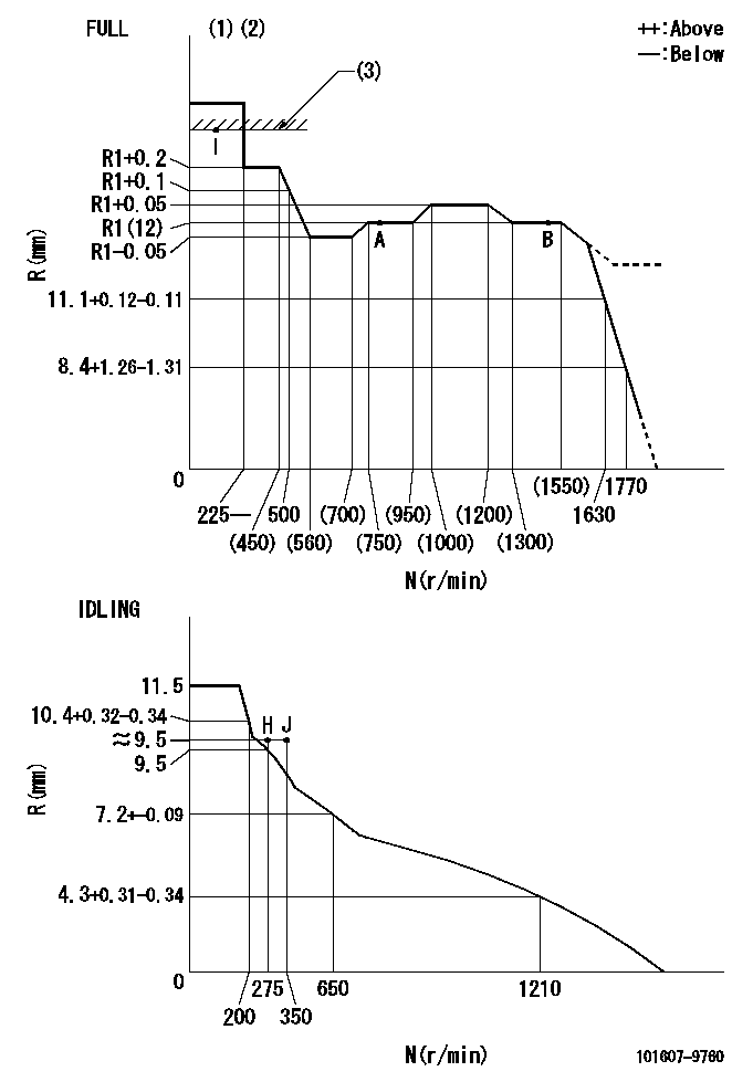
N:Pump speed
R:Rack position (mm)
(1)Torque cam stamping: T1
(2)Tolerance for racks not indicated: +-0.05mm.
(3)RACK LIMIT
----------
T1=L65
----------
----------
T1=L65
----------
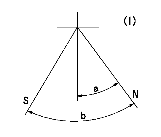
Speed control lever angle

F:Full speed
I:Idle
(1)Use the hole at R = aa
(2)Stopper bolt set position 'H'
----------
aa=36mm
----------
a=25deg+-5deg b=37deg+-3deg
----------
aa=36mm
----------
a=25deg+-5deg b=37deg+-3deg
Stop lever angle
N:Pump normal
S:Stop the pump.
(1)No return spring
----------
----------
a=20deg+-5deg b=40deg+-5deg
----------
----------
a=20deg+-5deg b=40deg+-5deg
0000001501 RACK SENSOR
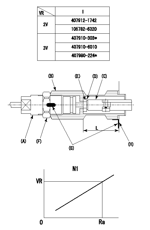
(VR) measurement voltage
(I) Part number of the control unit
(G) Apply red paint.
(H): End surface of the pump
1. Rack limit adjustment
(1)Fix the rack at the rack limit position Ra.
(2)Install the shim (D) to the rod (C) and tighten nut (E).
(3)Select a shim (D) so that the distance between the end surface of the pump and the nut (E) is L.
(4)Release the rack fixing and mount the joint (B) and fix.
(5)At this time, confirm that the shim (D) does not interfere with the joint (B).
2. Rack sensor adjustment (-0420)
(1)Screw in the bobbin (A) until it contacts the joint (B).
(2)Fix the speed control lever at the full side.
(3)Set the speed to N1 r/min.
(4)Adjust the depth that the bobbin (A) is screwed in so that the control unit's rack sensor output voltage is VR+-0.01 (V), then tighten the nut (F).
(5)Adjust the bobbin (A) so that the rack sensor's output voltage is VR.
(6)Apply G at two places.
Connecting part between the joint (B) and the nut (F)
Connecting part between the joint (B) and the end surface of the pump (H)
----------
L=33-0.2 mm N1=800r/min Ra=R1(12)mm
----------
----------
L=33-0.2 mm N1=800r/min Ra=R1(12)mm
----------
Timing setting

(1)Pump vertical direction
(2)Position of timer's threaded hole at No 1 cylinder's beginning of injection
(3)-
(4)-
----------
----------
a=(60deg)
----------
----------
a=(60deg)
Information:
Tooling and Equipment
The tools shown in Chart F, Tooling for Finding Top Center (TC) Position, are required to complete the procedure.
Table 8
Chart F
Tooling For Finding Top Center (TC) Position
Part No Description Qty Item (1)
8T-4177 Bolt, Spring Compressor 1 7
( 1 ) Refer to the nomenclature chart at the beginning of this manual for item identification.Procedure
Illustration 39 g03425683
Timing Bolt Location (35) 8T-4177 Timing Bolt (36) Timing Hole (37) Flywheel HousingNote: Depending on engine application, timing hole (36) is located at either the left front face or the right front face of the flywheel housing.
Remove plug from the timing hole (36) on the front of the flywheel housing.
Rotate the engine with four large bolts on the front of the crankshaft. Do not use the eight small bolts on the front of the crankshaft pulley as this could cause damage to the engine.
Put 8T-4177 Bolt (35) in hole. Turn the engine flywheel counterclockwise until the timing bolt engages with the threaded hole in the flywheel.Note: If the flywheel is turned beyond the point the timing bolt engages in the threaded hole, the flywheel must be turned back at least 30 degrees clockwise. Again, turn the flywheel counterclockwise until the timing bolt engages with the threaded hole. This procedure makes sure that the play is removed from the gears when number 1 piston is put on TC.
Remove the cylinder head valve cover.
Illustration 40 g03425694
Valve Cover Removed
The intake and the exhaust valves for the number 1 cylinder are fully closed if number 1 piston is on the compression stroke and the rocker arms can be moved by hand. If the rocker arms cannot be moved and the valves are slightly open, the number 1 piston is on the exhaust strike. Refer to Chart E, Crankshaft Positions for Fuel Timing Settings, to determine which cylinders can be checked/adjusted (determined by stroke position of crankshaft when timing bolt is installed).Note: When the actual stroke position is identified, and the other stroke position is desired, it is necessary to remove the timing bolt from the flywheel. Turn the flywheel counterclockwise 360 degrees, and reinstall the timing bolt.
After TC position for a particular stroke is obtained and adjustments are made, remove the timing bolt and turn the flywheel counterclockwise 360 degrees. This will put number 1 piston at TC position on the other stroke. Install timing bolt in the flywheel and complete adjustments for remaining cylinders.Removal and Installation of Unit Fuel Injectors
Table 9
Chart G
Injector Removal and Installation Tools
Part No Description Qty Item (1)
5P-0302 Injector Removal Bar 1 16
194-3542 Hex Socket Bit Driver, 5 mm 1 18
( 1 ) Refer to nomenclature chart, at the beginning of this manual for item identification.
Illustration 41 g03425701
Unit Fuel Injector (48) Bolt (49) O-RingsNote: Not all injectors use a bottom O-ring.Removal
Remove injector hold down bolt (48) .
Do not pry on the injector hold down bracket.