Information injection-pump assembly
ZEXEL
101607-9520
1016079520

Rating:
Cross reference number
ZEXEL
101607-9520
1016079520
Zexel num
Bosch num
Firm num
Name
101607-9520
DPICO
INJECTION-PUMP ASSEMBLY
6D16 * Q
6D16 * Q
Calibration Data:
Adjustment conditions
Test oil
1404 Test oil ISO4113 or {SAEJ967d}
1404 Test oil ISO4113 or {SAEJ967d}
Test oil temperature
degC
40
40
45
Nozzle and nozzle holder
105780-8140
Bosch type code
EF8511/9A
Nozzle
105780-0000
Bosch type code
DN12SD12T
Nozzle holder
105780-2080
Bosch type code
EF8511/9
Opening pressure
MPa
17.2
Opening pressure
kgf/cm2
175
Injection pipe
Outer diameter - inner diameter - length (mm) mm 6-2-600
Outer diameter - inner diameter - length (mm) mm 6-2-600
Overflow valve
131424-5520
Overflow valve opening pressure
kPa
255
221
289
Overflow valve opening pressure
kgf/cm2
2.6
2.25
2.95
Tester oil delivery pressure
kPa
157
157
157
Tester oil delivery pressure
kgf/cm2
1.6
1.6
1.6
Direction of rotation (viewed from drive side)
Left L
Left L
Injection timing adjustment
Direction of rotation (viewed from drive side)
Left L
Left L
Injection order
1-5-3-6-
2-4
Pre-stroke
mm
3.3
3.25
3.35
Beginning of injection position
Governor side NO.1
Governor side NO.1
Difference between angles 1
Cal 1-5 deg. 60 59.5 60.5
Cal 1-5 deg. 60 59.5 60.5
Difference between angles 2
Cal 1-3 deg. 120 119.5 120.5
Cal 1-3 deg. 120 119.5 120.5
Difference between angles 3
Cal 1-6 deg. 180 179.5 180.5
Cal 1-6 deg. 180 179.5 180.5
Difference between angles 4
Cyl.1-2 deg. 240 239.5 240.5
Cyl.1-2 deg. 240 239.5 240.5
Difference between angles 5
Cal 1-4 deg. 300 299.5 300.5
Cal 1-4 deg. 300 299.5 300.5
Injection quantity adjustment
Adjusting point
B
Rack position
10.1
Pump speed
r/min
750
750
750
Average injection quantity
mm3/st.
51.7
50.7
52.7
Max. variation between cylinders
%
0
-2.5
2.5
Basic
*
Fixing the lever
*
Injection quantity adjustment_02
Adjusting point
C
Rack position
8.8+-0.5
Pump speed
r/min
285
285
285
Average injection quantity
mm3/st.
10
8.5
11.5
Max. variation between cylinders
%
0
-15
15
Fixing the rack
*
Injection quantity adjustment_03
Adjusting point
D
Rack position
-
Pump speed
r/min
100
100
100
Average injection quantity
mm3/st.
71
61
81
Fixing the lever
*
Rack limit
*
Timer adjustment
Pump speed
r/min
1200++
Advance angle
deg.
0
0
0
Remarks
Do not advance until starting N = 1200.
Do not advance until starting N = 1200.
Timer adjustment_02
Pump speed
r/min
-
Advance angle
deg.
1.5
1.5
1.5
Remarks
Measure the actual speed, stop
Measure the actual speed, stop
Test data Ex:
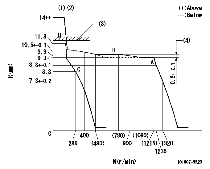
Governor adjustment

N:Pump speed
R:Rack position (mm)
(1)Target notch: K
(2)Tolerance for racks not indicated: +-0.05mm.
(3)RACK LIMIT
(4)Rack difference between N = N1 and N = N2
----------
K=16 N1=1200r/min N2=750r/min
----------
----------
K=16 N1=1200r/min N2=750r/min
----------
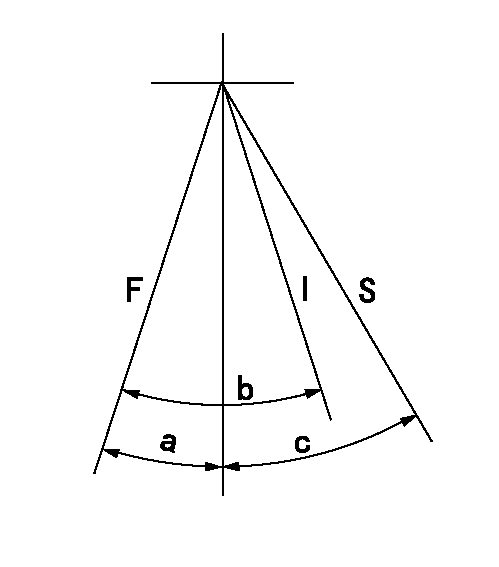
Speed control lever angle

F:Full speed
I:Idle
S:Stop
----------
----------
a=19deg+-5deg b=19deg+-5deg c=35deg+-3deg
----------
----------
a=19deg+-5deg b=19deg+-5deg c=35deg+-3deg
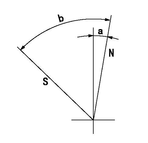
Stop lever angle

N:Pump normal
S:Stop the pump.
----------
----------
a=2.5deg+-5deg b=53deg+-5deg
----------
----------
a=2.5deg+-5deg b=53deg+-5deg
Timing setting

(1)Pump vertical direction
(2)Position of timer's tooth at No 1 cylinder's beginning of injection
(3)B.T.D.C.: aa
(4)-
----------
aa=18deg
----------
a=(2deg)
----------
aa=18deg
----------
a=(2deg)
Information:
Installing the Red LED Lamp (Regeneration Disable Lamp)
Illustration 1 g02402796
242-3282 Led Lamp As Use 155-2269 Connector Plug As as a mating connector. 155-2269 Connector Plug As is not included in the kit. Also, 102-8802 Receptacle Kit contains 3E-3364 Receptacle and 3E-3365 Receptacle Lock Wedge .
Insert the red (power) wire from the 242-3282 LED Lamp As into terminal 1 of 3E-3364 Receptacle .
Insert the black (ground) wire from the LED lamp into terminal 2 of the receptacle.
Insert 3E-3365 Receptacle Lock Wedge is the receptacle.
Connect terminal 1 of the receptacle to terminal 13 of 160-7689 Connector Plug As .
Connect terminal 2 of the receptacle to the ground/return (-).Installing the Illuminated Plug (Regeneration Lamp)
Illustration 2 g02402326
332-1064 Illuminated Plug The terminal designations can be found on the sides of 332-1064 Illuminated Plug and 205-5471 Connector .
Connect terminal 1A of the connector to the battery power (+).
Connect terminal 2A of the connector to the battery power (+).
Connect terminal 1B of the connector to terminal 30 of the plug.
Connect terminal 2B of the connector to terminal 31 of the plug.
Crimp the 112-9611 Blade Terminal onto the wires necessary to create the connections described in the previous steps.
Insert the blade terminals into the appropriate terminal locations of the connector.
Connect the plug to the connector. The plug and the connector are mating connectors.Installing the Hydraulic Lockout Rocker Switch (High Speed Regeneration Rocker Switch)
Illustration 3 g02366857
284-3623 Rocker Switch The terminal designations can be found on the sides of the 223-4778 Connector Plug As .
Insert 288-7146 Wire As into terminals 2,3,5, and 9 of the plug.
Splice the unoccupied ends of two 288-7146 Wire As together. Insert the spliced wire to provide a connection for terminal 6 to terminal 7 of 223-4778 Connector Plug As .
Connect terminal 2 of 223-4778 Connector Plug As to terminal 18 of 160-7689 Connector Plug As .
Connect
Have questions with 101607-9520?
Group cross 101607-9520 ZEXEL
Dpico
101607-9520
INJECTION-PUMP ASSEMBLY
6D16
6D16