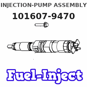
Information injection-pump assembly
BOSCH
9 400 615 759
9400615759
ZEXEL
101607-9470
1016079470
Rating:
Include in #2:
104138-1022
as _
Cross reference number
BOSCH
9 400 615 759
9400615759
ZEXEL
101607-9470
1016079470
Zexel num
Bosch num
Firm num
Name
101607-9470
9 400 615 759
DAEWOO
INJECTION-PUMP ASSEMBLY
DB58 * K
DB58 * K
Calibration Data:
Adjustment conditions
Test oil
1404 Test oil ISO4113 or {SAEJ967d}
1404 Test oil ISO4113 or {SAEJ967d}
Test oil temperature
degC
40
40
45
Nozzle and nozzle holder
105780-8140
Bosch type code
EF8511/9A
Nozzle
105780-0000
Bosch type code
DN12SD12T
Nozzle holder
105780-2080
Bosch type code
EF8511/9
Opening pressure
MPa
17.2
Opening pressure
kgf/cm2
175
Injection pipe
Outer diameter - inner diameter - length (mm) mm 6-2-600
Outer diameter - inner diameter - length (mm) mm 6-2-600
Overflow valve
131424-1520
Overflow valve opening pressure
kPa
157
123
191
Overflow valve opening pressure
kgf/cm2
1.6
1.25
1.95
Tester oil delivery pressure
kPa
157
157
157
Tester oil delivery pressure
kgf/cm2
1.6
1.6
1.6
Direction of rotation (viewed from drive side)
Right R
Right R
Injection timing adjustment
Direction of rotation (viewed from drive side)
Right R
Right R
Injection order
1-5-3-6-
2-4
Pre-stroke
mm
3.6
3.55
3.65
Beginning of injection position
Drive side NO.1
Drive side NO.1
Difference between angles 1
Cal 1-5 deg. 60 59.5 60.5
Cal 1-5 deg. 60 59.5 60.5
Difference between angles 2
Cal 1-3 deg. 120 119.5 120.5
Cal 1-3 deg. 120 119.5 120.5
Difference between angles 3
Cal 1-6 deg. 180 179.5 180.5
Cal 1-6 deg. 180 179.5 180.5
Difference between angles 4
Cyl.1-2 deg. 240 239.5 240.5
Cyl.1-2 deg. 240 239.5 240.5
Difference between angles 5
Cal 1-4 deg. 300 299.5 300.5
Cal 1-4 deg. 300 299.5 300.5
Injection quantity adjustment
Adjusting point
-
Rack position
11.1
Pump speed
r/min
1000
1000
1000
Average injection quantity
mm3/st.
73.5
71.9
75.1
Max. variation between cylinders
%
0
-2.5
2.5
Basic
*
Fixing the rack
*
Standard for adjustment of the maximum variation between cylinders
*
Injection quantity adjustment_02
Adjusting point
H
Rack position
9.5+-0.5
Pump speed
r/min
275
275
275
Average injection quantity
mm3/st.
9
7.7
10.3
Max. variation between cylinders
%
0
-14
14
Fixing the rack
*
Standard for adjustment of the maximum variation between cylinders
*
Injection quantity adjustment_03
Adjusting point
A
Rack position
R1(11.1)
Pump speed
r/min
1000
1000
1000
Average injection quantity
mm3/st.
73.5
72.5
74.5
Basic
*
Fixing the lever
*
Injection quantity adjustment_04
Adjusting point
B
Rack position
R1+0.9
Pump speed
r/min
1600
1600
1600
Average injection quantity
mm3/st.
94
90
98
Fixing the lever
*
Injection quantity adjustment_05
Adjusting point
I
Rack position
-
Pump speed
r/min
100
100
100
Average injection quantity
mm3/st.
90
90
100
Fixing the lever
*
Rack limit
*
Timer adjustment
Pump speed
r/min
1050--
Advance angle
deg.
0
0
0
Remarks
Start
Start
Timer adjustment_02
Pump speed
r/min
1000
Advance angle
deg.
0.5
Timer adjustment_03
Pump speed
r/min
1520
Advance angle
deg.
6
5.5
6.5
Remarks
Finish
Finish
Test data Ex:
Governor adjustment
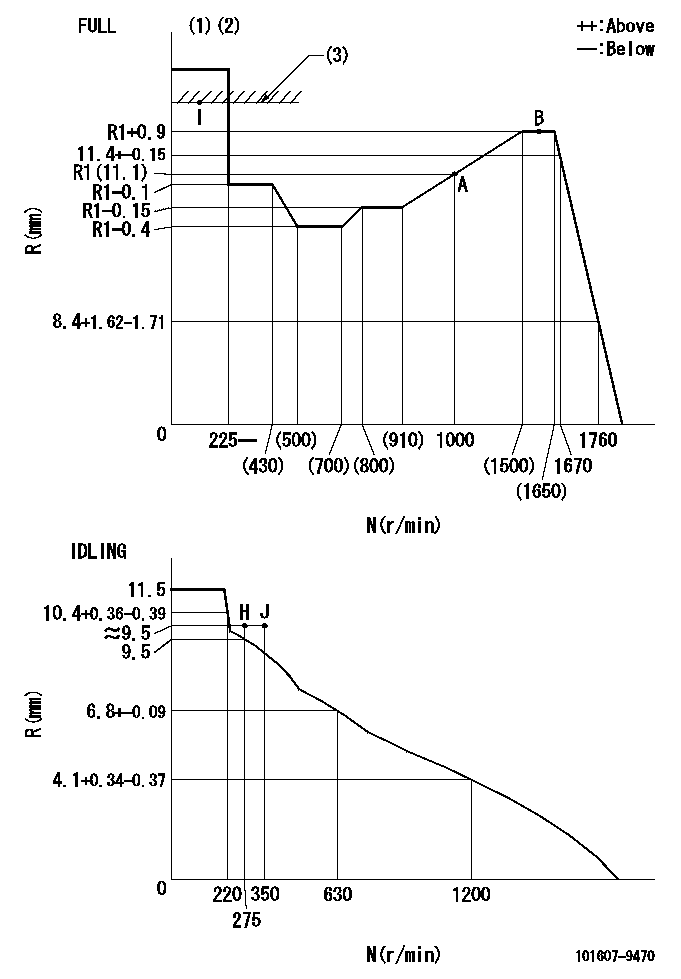
N:Pump speed
R:Rack position (mm)
(1)Torque cam stamping: T1
(2)Tolerance for racks not indicated: +-0.05mm.
(3)RACK LIMIT
----------
T1=K82
----------
----------
T1=K82
----------
Speed control lever angle
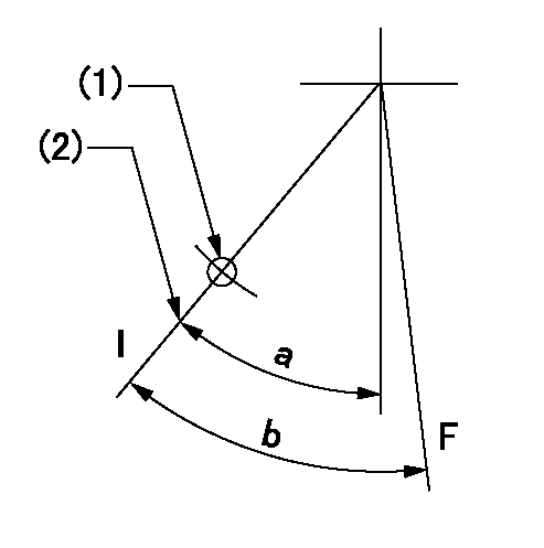
F:Full speed
I:Idle
(1)Use the hole at R = aa
(2)Stopper bolt set position 'H'
----------
aa=35mm
----------
a=40deg+-5deg b=(42deg)+-3deg
----------
aa=35mm
----------
a=40deg+-5deg b=(42deg)+-3deg
Stop lever angle
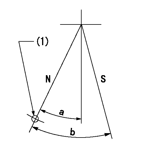
N:Pump normal
S:Stop the pump.
(1)Use the hole at R = aa
----------
aa=45mm
----------
a=25deg+-5deg b=40deg+-5deg
----------
aa=45mm
----------
a=25deg+-5deg b=40deg+-5deg
Timing setting

(1)Pump vertical direction
(2)Coupling's key groove position at No 1 cylinder's beginning of injection
(3)B.T.D.C.: aa
(4)-
----------
aa=16deg
----------
a=(2deg)
----------
aa=16deg
----------
a=(2deg)
Information:
Introduction
Do not perform any procedure that is outlined in this Special Instruction until you have read and understand the information contained in this document.Required Parts
Table 1
Required Parts
Item Qty Part Number Part Name
1 1 360-9664 Tool Kit
2 1 399-7930 Cap Kit Testing Procedure
Use Caterpillar Electronic Technician (ET) to perform a "Manual Diesel Particulate Filter Regeneration".
Once the regeneration is complete, wait for the engine to drop to idle before shutting off the engine. The regeneration takes approximately 20 minutes.
Allow the system to cool down before handling.
While waiting for the exhaust to cool, perform the following actions.
Record the "Idle Speed Limit". Use Cat ET to change the "Idle RPM Limit" to 2100 rpm.
Use Cat ET to disable the automatic regeneration. A "Check Engine" light with active code 3714-31 will be present.
Remove the exhaust piping after the DPF. Install the 3 inch orifice plate for C13 and C15 engines. Install the 2 inch orifice plate for C7 and C9 engines. The 2 inch orifice plate is part of the 399-7930 Cap Kit .For a DPF with a dual outlet, use the solid cap that is provided and cap one of the outlets.For a dual DPF with one end cap, use a 313-3496 Plug to plug the drain hole, one 3L-7055 Pipe Connector , one 001-6449 Connector , and filter paper. Remove the delta P sensor from each DPF. Insert one 3L-7055 Pipe Connector , one 001-6449 Connector , and filter paper into each DPF. This action allows both diesel particulate filters to be tested at the same time.Note: The 313-3496 Plug , the 001-6449 Connector , and the 3L-7055 Pipe Connector is not included in the kit.
Start the engine. Run the engine at 2100 rpm for a minimum of 10 minutes to stabilize DPF temperatures.
Shut down the engine and install the filter holder in the drain port.Note: Do not wait more than 10 minutes after the engine has shut down to install the filter.
Run the engine at 2100 rpm for 20 minutes.
Shut down the engine and remove the filter holder. Use proper personal protective equipment to remove the filter holder.Note: Do not wait more than 10 minutes after the engine has shut down to remove the filter holder.
Warning: The filter holder will still be hot.
Wait for the filter holder to cool down before disassembly.
Carefully disassemble the filter holder to prevent contamination.
Tip the fitting over on a clean surface to remove the filter paper.
Handle the filter paper with clean hands. Only handle the filter paper by the edges.
Compare the stained area in the center of the filter paper to the color coded sheet that is provided.If the stained area of the filter paper is as dark or darker than colored circle 2, then the DPF may have to be replaced.If a DPF fails the test, then contact the DPF hotline to verify the failure and have a new DPF released.
Have questions with 101607-9470?
Group cross 101607-9470 ZEXEL
Nissan-Diesel
Dpico
Nissan-Diesel
Daewoo
101607-9470
9 400 615 759
INJECTION-PUMP ASSEMBLY
DB58
DB58