Information injection-pump assembly
ZEXEL
101607-9450
1016079450
NISSAN-DIESEL
16713Z6506
16713z6506
Rating:
Cross reference number
ZEXEL
101607-9450
1016079450
NISSAN-DIESEL
16713Z6506
16713z6506
Zexel num
Bosch num
Firm num
Name
Calibration Data:
Adjustment conditions
Test oil
1404 Test oil ISO4113 or {SAEJ967d}
1404 Test oil ISO4113 or {SAEJ967d}
Test oil temperature
degC
40
40
45
Nozzle and nozzle holder
105780-8260
Bosch type code
9 430 610 133
Nozzle
105780-0120
Bosch type code
1 688 901 990
Nozzle holder
105780-2190
Opening pressure
MPa
18
Opening pressure
kgf/cm2
184
Injection pipe
Outer diameter - inner diameter - length (mm) mm 6-2-600
Outer diameter - inner diameter - length (mm) mm 6-2-600
Overflow valve
131425-0420
Overflow valve opening pressure
kPa
157
123
191
Overflow valve opening pressure
kgf/cm2
1.6
1.25
1.95
Tester oil delivery pressure
kPa
255
255
255
Tester oil delivery pressure
kgf/cm2
2.6
2.6
2.6
Direction of rotation (viewed from drive side)
Right R
Right R
Injection timing adjustment
Direction of rotation (viewed from drive side)
Right R
Right R
Injection order
1-4-2-6-
3-5
Pre-stroke
mm
3.7
3.65
3.75
Beginning of injection position
Drive side NO.1
Drive side NO.1
Difference between angles 1
Cal 1-4 deg. 60 59.5 60.5
Cal 1-4 deg. 60 59.5 60.5
Difference between angles 2
Cyl.1-2 deg. 120 119.5 120.5
Cyl.1-2 deg. 120 119.5 120.5
Difference between angles 3
Cal 1-6 deg. 180 179.5 180.5
Cal 1-6 deg. 180 179.5 180.5
Difference between angles 4
Cal 1-3 deg. 240 239.5 240.5
Cal 1-3 deg. 240 239.5 240.5
Difference between angles 5
Cal 1-5 deg. 300 299.5 300.5
Cal 1-5 deg. 300 299.5 300.5
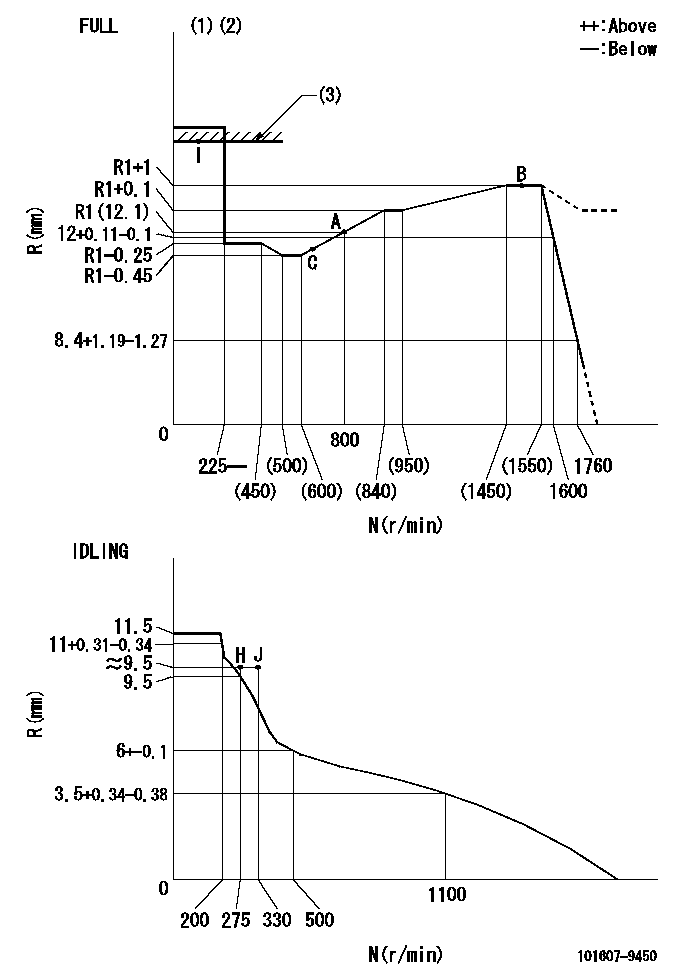
Injection quantity adjustment
Adjusting point
-
Rack position
12.1
Pump speed
r/min
800
800
800
Average injection quantity
mm3/st.
99
97.4
100.6
Max. variation between cylinders
%
0
-3.5
3.5
Basic
*
Fixing the rack
*
Standard for adjustment of the maximum variation between cylinders
*
Injection quantity adjustment_02
Adjusting point
Z
Rack position
9.5+-0.5
Pump speed
r/min
265
265
265
Average injection quantity
mm3/st.
9
7.2
10.8
Max. variation between cylinders
%
0
-10
10
Fixing the rack
*
Standard for adjustment of the maximum variation between cylinders
*
Injection quantity adjustment_03
Adjusting point
A
Rack position
R1(12.1)
Pump speed
r/min
800
800
800
Average injection quantity
mm3/st.
99
98
100
Basic
*
Fixing the lever
*
Injection quantity adjustment_04
Adjusting point
B
Rack position
R1+1
Pump speed
r/min
1500
1500
1500
Average injection quantity
mm3/st.
105.5
101.5
109.5
Fixing the lever
*
Injection quantity adjustment_05
Adjusting point
C
Rack position
(R1-0.45
)
Pump speed
r/min
600
600
600
Average injection quantity
mm3/st.
94.5
90.5
98.5
Fixing the lever
*
Injection quantity adjustment_06
Adjusting point
I
Rack position
-
Pump speed
r/min
100
100
100
Average injection quantity
mm3/st.
105
105
115
Fixing the lever
*
Rack limit
*
Timer adjustment
Pump speed
r/min
(900)
Advance angle
deg.
0
0
0
Remarks
Start
Start
Timer adjustment_02
Pump speed
r/min
1080
Advance angle
deg.
2
1.5
2.5
Timer adjustment_03
Pump speed
r/min
1225
Advance angle
deg.
2
1.5
2.5
Timer adjustment_04
Pump speed
r/min
1425
Advance angle
deg.
6
5.5
6.5
Remarks
Finish
Finish
Test data Ex:
Governor adjustment
N:Pump speed
R:Rack position (mm)
(1)Torque cam stamping: T1
(2)Tolerance for racks not indicated: +-0.05mm.
(3)RACK LIMIT
----------
T1=K89
----------
----------
T1=K89
----------
Speed control lever angle

F:Full speed
I:Idle
(1)Use the hole at R = aa
(2)Stopper bolt set position 'H'
----------
aa=39mm
----------
a=20deg+-5deg b=42deg+-3deg
----------
aa=39mm
----------
a=20deg+-5deg b=42deg+-3deg
Stop lever angle
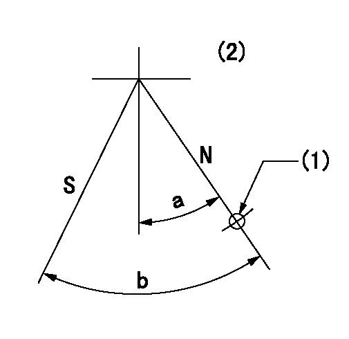
N:Pump normal
S:Stop the pump.
(1)Use the hole at R = aa
(2)No return spring
----------
aa=28mm
----------
a=20deg+-5deg b=40deg+-5deg
----------
aa=28mm
----------
a=20deg+-5deg b=40deg+-5deg
0000001501 LEVER
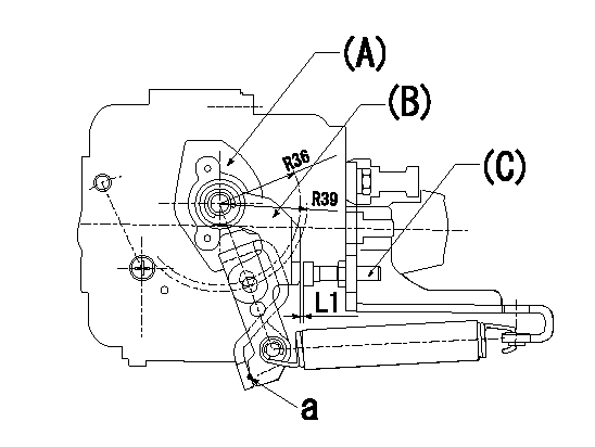
(a) Speed lever
(B) Accelerator lever
(C) Accelerator lever stopper bolt
1. Accelerator lever setting method
With the speed lever in the idling position, back off the accelerator lever stopper bolt L1 from where it contacts point a. (Back off 1+0.5 turns and set.)
----------
L1=1+0.5mm
----------
----------
L1=1+0.5mm
----------
Timing setting

(1)Pump vertical direction
(2)Position of timer's threaded hole at No 1 cylinder's beginning of injection
(3)-
(4)-
----------
----------
a=(60deg)
----------
----------
a=(60deg)
Information:
Literature Information
This manual should be stored in the operator's compartment in the literature holder or seat back literature storage area.This manual contains safety information, operation instructions, and maintenance recommendations.Some photographs or illustrations in this publication show details or attachments that can be different from your machine.Continuing improvement and advancement of product design might have caused changes to your machine which are not included in this publication. Read, study and keep this manual with the machine.Whenever a question arises regarding your machine, or this publication, please consult your Cat dealer for the latest available information.Safety
The safety section lists basic safety precautions. In addition, this section identifies the text and locations of warning signs and labels used on the machine.Operation
The operation section is a reference for the new operator and a refresher for the experienced operator. This section includes a discussion of gauges, switches, machine controls, attachment controls, and programming information.Photographs and illustrations guide the operator through correct procedures of checking, starting, operating and stopping the machine.Operating techniques outlined in this publication are basic. Skill and techniques develop as the operator gains knowledge of the machine and its capabilities.Maintenance
The maintenance section is a guide to equipment care.California Proposition 65 Warning
Diesel engine exhaust and some of its constituents are known to the State of California to cause cancer, birth defects, and other reproductive harm.Battery posts, terminals and related accessories contain lead and lead compounds.Wash hands after handlingCertified Engine Maintenance
Proper maintenance and repair is essential to keep the engine and machine systems operating correctly. As the heavy duty off-road diesel engine owner, you are responsible for the performance of the required maintenance listed in the Owner's Manual, Operation and Maintenance Manual, and Service Manual.It is prohibited for any person engaged in the business of repairing, servicing, selling, leasing, or trading engines or machines to remove, alter, or render inoperative any emission related device or element of design installed on or in an engine or machine that is in compliance with the regulations (40 CFR Part 89). Certain elements of the machine and engine such as the exhaust system, fuel system, electrical system, intake air system and cooling system may be emission related and should not be altered unless approved by Caterpillar.Cat Product Identification Number
Effective First Quarter 2001 the Cat Product Identification Number (PIN) will change from 8 to 17 characters. In an effort to provide uniform equipment identification, Caterpillar and other construction equipment manufacturers are moving to comply with the latest version of the product identification numbering standard. Non-road machine PINs are defined by ISO 10261. The new PIN format will apply to all Cat machines and generator sets. The PIN plates and frame marking will display the 17 character PIN. The new format will look like the following:
Illustration 1 g00751314Where:1. Caterpillar's World Manufacturing Code (characters 1-3)2. Machine Descriptor (characters 4-8)3. Check Character (character 9)4. Machine Indicator Section (MIS) or Product Sequence Number (characters 10-17). These were previously referred to as the Serial Number.Machines and generator sets produced before First Quarter 2001 will