Information injection-pump assembly
BOSCH
F 019 Z20 006
f019z20006
ZEXEL
101607-9430
1016079430

Rating:
Include in #1:
101402-7990
as _
Cross reference number
BOSCH
F 019 Z20 006
f019z20006
ZEXEL
101607-9430
1016079430
Zexel num
Bosch num
Firm num
Name
101607-9430
F 019 Z20 006
DPICO
INJECTION-PUMP ASSEMBLY
6D22 Q
6D22 Q
Calibration Data:
Adjustment conditions
Test oil
1404 Test oil ISO4113 or {SAEJ967d}
1404 Test oil ISO4113 or {SAEJ967d}
Test oil temperature
degC
40
40
45
Nozzle and nozzle holder
105780-8140
Bosch type code
EF8511/9A
Nozzle
105780-0000
Bosch type code
DN12SD12T
Nozzle holder
105780-2080
Bosch type code
EF8511/9
Opening pressure
MPa
17.2
Opening pressure
kgf/cm2
175
Injection pipe
Outer diameter - inner diameter - length (mm) mm 6-2-600
Outer diameter - inner diameter - length (mm) mm 6-2-600
Overflow valve
131424-5120
Overflow valve opening pressure
kPa
255
221
289
Overflow valve opening pressure
kgf/cm2
2.6
2.25
2.95
Tester oil delivery pressure
kPa
157
157
157
Tester oil delivery pressure
kgf/cm2
1.6
1.6
1.6
Direction of rotation (viewed from drive side)
Right R
Right R
Injection timing adjustment
Direction of rotation (viewed from drive side)
Right R
Right R
Injection order
1-5-3-6-
2-4
Pre-stroke
mm
4.5
4.45
4.55
Beginning of injection position
Governor side NO.1
Governor side NO.1
Difference between angles 1
Cal 1-5 deg. 60 59.5 60.5
Cal 1-5 deg. 60 59.5 60.5
Difference between angles 2
Cal 1-3 deg. 120 119.5 120.5
Cal 1-3 deg. 120 119.5 120.5
Difference between angles 3
Cal 1-6 deg. 180 179.5 180.5
Cal 1-6 deg. 180 179.5 180.5
Difference between angles 4
Cyl.1-2 deg. 240 239.5 240.5
Cyl.1-2 deg. 240 239.5 240.5
Difference between angles 5
Cal 1-4 deg. 300 299.5 300.5
Cal 1-4 deg. 300 299.5 300.5
Injection quantity adjustment
Adjusting point
-
Rack position
9.6
Pump speed
r/min
700
700
700
Each cylinder's injection qty
mm3/st.
112
109.2
114.8
Basic
*
Fixing the rack
*
Standard for adjustment of the maximum variation between cylinders
*
Injection quantity adjustment_02
Adjusting point
C
Rack position
6.8+-0.5
Pump speed
r/min
450
450
450
Each cylinder's injection qty
mm3/st.
20
17
23
Fixing the rack
*
Standard for adjustment of the maximum variation between cylinders
*
Injection quantity adjustment_03
Adjusting point
A
Rack position
R1(9.6)
Pump speed
r/min
700
700
700
Average injection quantity
mm3/st.
112
111
113
Basic
*
Fixing the lever
*
Injection quantity adjustment_04
Adjusting point
E
Rack position
-
Pump speed
r/min
100
100
100
Average injection quantity
mm3/st.
125
85
165
Fixing the lever
*
Remarks
After startup boost setting
After startup boost setting
Injection quantity adjustment_05
Adjusting point
F
Rack position
7.3+-0.5
Pump speed
r/min
335
335
335
Average injection quantity
mm3/st.
16
14.5
17.5
Fixing the rack
*
Timer adjustment
Pump speed
r/min
950--
Advance angle
deg.
0
0
0
Remarks
Start
Start
Timer adjustment_02
Pump speed
r/min
900
Advance angle
deg.
0.5
Timer adjustment_03
Pump speed
r/min
1150
Advance angle
deg.
4.5
4
5
Remarks
Finish
Finish
Test data Ex:
Governor adjustment
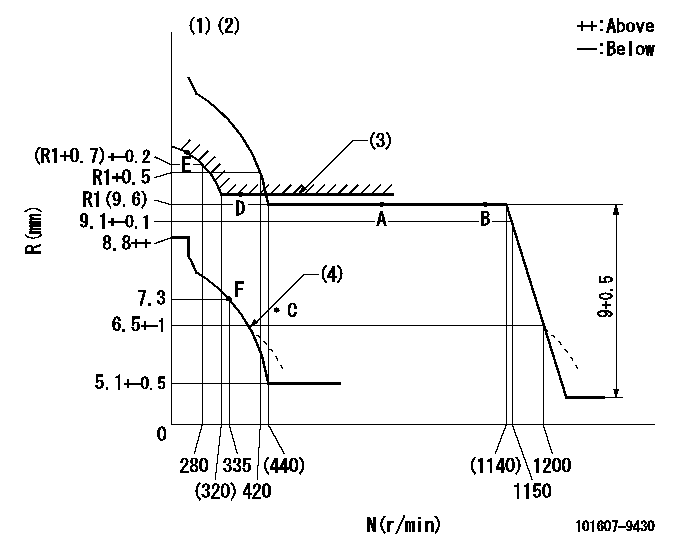
N:Pump speed
R:Rack position (mm)
(1)Microswitch not operating at delivery.
(2)Tolerance for racks not indicated: +-0.05mm.
(3)Excess fuel setting for starting: SXL (N = N1)
(4)Damper spring setting: DL
----------
SXL=(R1+0.1)+0.2mm N1=350r/min DL=6-0.2mm
----------
----------
SXL=(R1+0.1)+0.2mm N1=350r/min DL=6-0.2mm
----------
Speed control lever angle

F:Full speed
----------
----------
a=(1deg)+-5deg
----------
----------
a=(1deg)+-5deg
0000000901
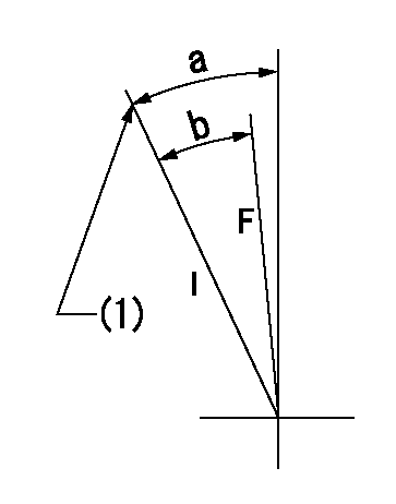
F:Full load
I:Idle
(1)Stopper bolt setting
----------
----------
a=19deg+-5deg b=16.5deg+-3deg
----------
----------
a=19deg+-5deg b=16.5deg+-3deg
Stop lever angle
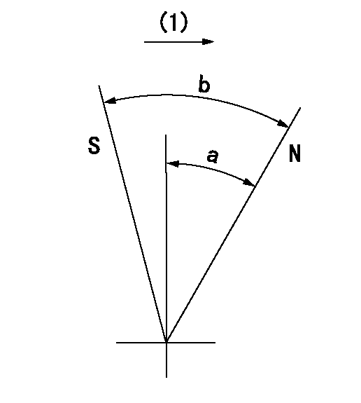
N:Pump normal
S:Stop the pump.
(1)Drive side
----------
----------
a=54deg+-5deg b=71deg+-5deg
----------
----------
a=54deg+-5deg b=71deg+-5deg
Timing setting

(1)Pump vertical direction
(2)Coupling's key groove position at No 1 cylinder's beginning of injection
(3)B.T.D.C.: aa
(4)-
----------
aa=15deg
----------
a=(7deg)
----------
aa=15deg
----------
a=(7deg)
Information:
Table 1
Required Parts
Qty Part Number Part Name Former Part Number
1 494-6233 Injector 307-3245(1)
(1) The former part number listed is for reference only and may differ.
Do not operate or work on this product unless you have read and understood the instruction and warnings in the relevant Operation and Maintenance Manuals and relevant service literature. Failure to follow the instructions or heed the warnings could result in injury or death. Proper care is your responsibility.
"The improved autolube injector requires a new adjustment sleeve. Follow the procedure below for the selection and adjustment of the sleeve.Changing the Metering Unit
Illustration 1 g06607746
(A) Adjustment Screw
(B) Locknut
(C) Adjustment Sleeve
Table 2
Adjustment Sleeves
Caterpillar Part Number Part Name Output cc Sleeve Color
494-6245 Sleeve 0.25 cc (0.015 cubic inch) Pink
494-6241 Sleeve 0.50 cc (0.030 cubic inch) Red
494-6242 Sleeve 0.750 cc (0.045 cubic inch) Silver
494-6243 Sleeve 1.00 cc (0.06 cubic inch) Gold
494-6244 Sleeve 1.25 cc (0.075 cubic inch) Green The automatic lubrication system offers the ability to change the amount of grease that is supplied per cycle to each grease point. Changing the grease supply amount is completed by adjusting locknut (B) or replacing adjustment sleeve (C) on the injector. See Table 2 for reference.There is a set of color-coded anodized aluminum adjustment sleeves (C) available for various lubrication dispensing amounts. Adjustment sleeves (C) provide an easy way to adjust the output of the injectors and provide a clear indication of the output setting. Adjustment sleeves (C) allow for easy system installation and preventative maintenance.Install adjustment sleeves (C) by doing the following Steps below:
Remove and discard locknut (B).
Place adjustment sleeve (C) on adjustment screw (A).
Tighten adjustment screw (A) to 6.7 N m (60 lb in).
Have questions with 101607-9430?
Group cross 101607-9430 ZEXEL
Nissan-Diesel
Dpico
101607-9430
F 019 Z20 006
INJECTION-PUMP ASSEMBLY
6D22
6D22