Information injection-pump assembly
ZEXEL
101607-9420
1016079420
NISSAN-DIESEL
16713Z6504
16713z6504
Rating:
Cross reference number
ZEXEL
101607-9420
1016079420
NISSAN-DIESEL
16713Z6504
16713z6504
Zexel num
Bosch num
Firm num
Name
Calibration Data:
Adjustment conditions
Test oil
1404 Test oil ISO4113 or {SAEJ967d}
1404 Test oil ISO4113 or {SAEJ967d}
Test oil temperature
degC
40
40
45
Nozzle and nozzle holder
105780-8260
Bosch type code
9 430 610 133
Nozzle
105780-0120
Bosch type code
1 688 901 990
Nozzle holder
105780-2190
Opening pressure
MPa
18
Opening pressure
kgf/cm2
184
Injection pipe
Outer diameter - inner diameter - length (mm) mm 6-2-600
Outer diameter - inner diameter - length (mm) mm 6-2-600
Overflow valve
131425-0420
Overflow valve opening pressure
kPa
157
123
191
Overflow valve opening pressure
kgf/cm2
1.6
1.25
1.95
Tester oil delivery pressure
kPa
255
255
255
Tester oil delivery pressure
kgf/cm2
2.6
2.6
2.6
Direction of rotation (viewed from drive side)
Right R
Right R
Injection timing adjustment
Direction of rotation (viewed from drive side)
Right R
Right R
Injection order
1-4-2-6-
3-5
Pre-stroke
mm
3.7
3.65
3.75
Beginning of injection position
Drive side NO.1
Drive side NO.1
Difference between angles 1
Cal 1-4 deg. 60 59.5 60.5
Cal 1-4 deg. 60 59.5 60.5
Difference between angles 2
Cyl.1-2 deg. 120 119.5 120.5
Cyl.1-2 deg. 120 119.5 120.5
Difference between angles 3
Cal 1-6 deg. 180 179.5 180.5
Cal 1-6 deg. 180 179.5 180.5
Difference between angles 4
Cal 1-3 deg. 240 239.5 240.5
Cal 1-3 deg. 240 239.5 240.5
Difference between angles 5
Cal 1-5 deg. 300 299.5 300.5
Cal 1-5 deg. 300 299.5 300.5
Injection quantity adjustment
Adjusting point
-
Rack position
12.2
Pump speed
r/min
800
800
800
Average injection quantity
mm3/st.
101.5
99.9
103.1
Max. variation between cylinders
%
0
-3.5
3.5
Basic
*
Fixing the rack
*
Standard for adjustment of the maximum variation between cylinders
*
Injection quantity adjustment_02
Adjusting point
Z
Rack position
9.5+-0.5
Pump speed
r/min
275
275
275
Average injection quantity
mm3/st.
9
7.2
10.8
Max. variation between cylinders
%
0
-10
10
Fixing the rack
*
Standard for adjustment of the maximum variation between cylinders
*
Injection quantity adjustment_03
Adjusting point
A
Rack position
R1(12.2)
Pump speed
r/min
800
800
800
Average injection quantity
mm3/st.
101.5
100.5
102.5
Basic
*
Fixing the lever
*
Injection quantity adjustment_04
Adjusting point
B
Rack position
R1+1
Pump speed
r/min
1500
1500
1500
Average injection quantity
mm3/st.
107.5
103.5
111.5
Fixing the lever
*
Injection quantity adjustment_05
Adjusting point
C
Rack position
(R1-0.45
)
Pump speed
r/min
600
600
600
Average injection quantity
mm3/st.
97.5
93.5
101.5
Fixing the lever
*
Injection quantity adjustment_06
Adjusting point
I
Rack position
-
Pump speed
r/min
100
100
100
Average injection quantity
mm3/st.
120
120
130
Fixing the lever
*
Rack limit
*
Timer adjustment
Pump speed
r/min
975--
Advance angle
deg.
0
0
0
Remarks
Start
Start
Timer adjustment_02
Pump speed
r/min
925
Advance angle
deg.
0.5
Timer adjustment_03
Pump speed
r/min
(1000)
Advance angle
deg.
1
0.5
1.5
Remarks
Measure the actual speed.
Measure the actual speed.
Timer adjustment_04
Pump speed
r/min
1225
Advance angle
deg.
1
0.5
1.5
Timer adjustment_05
Pump speed
r/min
1300
Advance angle
deg.
3
3
3
Remarks
Measure the actual advance angle.
Measure the actual advance angle.
Timer adjustment_06
Pump speed
r/min
1450
Advance angle
deg.
6
5.5
6.5
Remarks
Finish
Finish
Test data Ex:
Governor adjustment
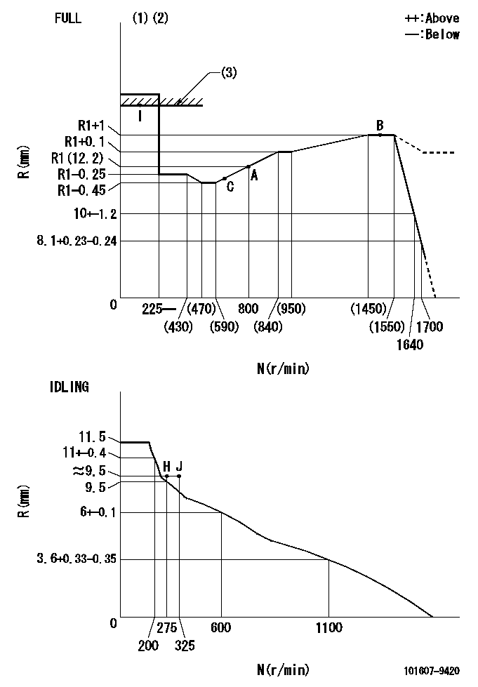
N:Pump speed
R:Rack position (mm)
(1)Torque cam stamping: T1
(2)Tolerance for racks not indicated: +-0.05mm.
(3)RACK LIMIT
----------
T1=K95
----------
----------
T1=K95
----------
Speed control lever angle

F:Full speed
I:Idle
(1)Use the hole at R = aa
(2)Stopper bolt set position 'H'
----------
aa=100mm
----------
a=26.5deg+-5deg b=(46deg)+-3deg
----------
aa=100mm
----------
a=26.5deg+-5deg b=(46deg)+-3deg
Stop lever angle
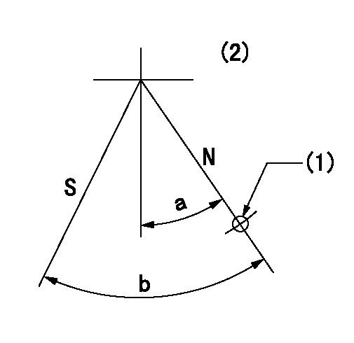
N:Pump normal
S:Stop the pump.
(1)Use the hole at R = aa
(2)No return spring
----------
aa=28mm
----------
a=20deg+-5deg b=40deg+-5deg
----------
aa=28mm
----------
a=20deg+-5deg b=40deg+-5deg
Timing setting

(1)Pump vertical direction
(2)Position of timer's threaded hole at No 1 cylinder's beginning of injection
(3)-
(4)-
----------
----------
a=(60deg)
----------
----------
a=(60deg)
Information:
Illustration 39 g03157737
Select "Engine Technical Marketing Information - TMI Web" under the "Additional Service Information" heading.Note: If "Engine Technical Marketing Information - TMI Web" is not visible, select "View More".
Illustration 40 g03817877
Input the serial number of the engine in "Reference Number" box (1).
Select "Serial Number" in drop-down menu (2).
Select "Retrieve Data" (3).
Illustration 41 g03817327
Select "Emissions Data" (4).
Select "Need emissions replacement label? Click here!" (5).Note: "Large Power Systems Division" window will now open.
Illustration 42 g03817878
Select "Recon Replacement Request".
Illustration 43 g03818933
Typical example - "Emissions/Certification Replacement" window
Fill in the required details:
Table 5
Emissions/Certification Replacement Window
Item Description
2 Enter the dealer name (code)
3 Enter "Machine"
4 Enter "C15" under Engine Sales Model
5 Enter the Engine Serial Number
6 Enter the media number of the Special Instruction
When all details are filled in, select "Submit".Note: Two labels and a serial number plate will be sent to the dealer address. If two labels are not received, contact Global_Engine_Marking.
Illustration 44 g03159376
Install the new emissions certification film (6), information label (7), and serial number plate on the cylinder block according to the installation instructions received with the labels and plate.Note: Destroy the old emissions certification film and serial number plate.Operation and Maintenance information
There are several specific messages on this machine. The exact location of the messages and the description of the messages are reviewed in this section. Become familiarized with all messages.Make sure that all of the messages are legible. Clean the messages or replace the messages if you cannot read the words. Replace the illustrations if the illustrations are not legible. When you clean the messages, use a cloth, water, and soap. Do not use solvent, gasoline, or other harsh chemicals to clean the messages. Solvents, gasoline, or harsh chemicals could loosen the adhesive that secures the messages. Loose adhesive will allow the messages to fall.Replace any message that is damaged, or missing. If a message is attached to a part that is replaced, install a message on the replacement part. Any Cat® dealer can provide new messages.
Illustration 45 g03501777
Location of films
(1) Engine Oil film
(2) Diesel Fuel Requirements filmEngine Oil (1)
This film is located next to the engine oil filler tube on the right side of the machine.
Illustration 46 g02448560Cat® DEO-ULS oils and oils that satisfy the "API CJ-4"and/or "ACEA E9" requirements are required for engines that are equipped with a diesel particulate filter.Diesel Fuel Requirements (2)
This film is located next to the fuel cap on the right side of the machine.
Illustration 47 g03619316Use Ultralow Sulfur Diesel (ULSD) fuel.The Environmental Protection Agency (EPA) defines Ultra-Low Sulfur Diesel (ULSD - S15) as “a diesel fuel with a sulfur content not to exceed 15 parts per million (ppm(mg/kg)) or 0.0015 percent by weight”. Engines are equipped with exhaust after-treatment systems are designed to run on ULSD only. Use of LSD or fuels higher than 15 ppm (mg/kg) sulfur in these engines will reduce engine efficiency and engine durability. Damage to the emissions control systems and/or shortened service interval will occur. Failures that result form the use of fuels are not Caterpillar factory defects. Therefore the cost of repairs would not be