Information injection-pump assembly
ZEXEL
101607-9220
1016079220
NISSAN-DIESEL
1671395276
1671395276

Rating:
Service parts 101607-9220 INJECTION-PUMP ASSEMBLY:
1.
_
7.
COUPLING PLATE
8.
_
9.
_
11.
Nozzle and Holder
16600-95019
12.
Open Pre:MPa(Kqf/cm2)
19.6{200}
15.
NOZZLE SET
Include in #1:
101607-9220
as INJECTION-PUMP ASSEMBLY
Include in #2:
104746-5200
as _
Cross reference number
ZEXEL
101607-9220
1016079220
NISSAN-DIESEL
1671395276
1671395276
Zexel num
Bosch num
Firm num
Name
Calibration Data:
Adjustment conditions
Test oil
1404 Test oil ISO4113 or {SAEJ967d}
1404 Test oil ISO4113 or {SAEJ967d}
Test oil temperature
degC
40
40
45
Nozzle and nozzle holder
105780-8140
Bosch type code
EF8511/9A
Nozzle
105780-0000
Bosch type code
DN12SD12T
Nozzle holder
105780-2080
Bosch type code
EF8511/9
Opening pressure
MPa
17.2
Opening pressure
kgf/cm2
175
Injection pipe
Outer diameter - inner diameter - length (mm) mm 6-2-600
Outer diameter - inner diameter - length (mm) mm 6-2-600
Overflow valve
131424-1520
Overflow valve opening pressure
kPa
157
123
191
Overflow valve opening pressure
kgf/cm2
1.6
1.25
1.95
Tester oil delivery pressure
kPa
157
157
157
Tester oil delivery pressure
kgf/cm2
1.6
1.6
1.6
Direction of rotation (viewed from drive side)
Right R
Right R
Injection timing adjustment
Direction of rotation (viewed from drive side)
Right R
Right R
Injection order
1-4-2-6-
3-5
Pre-stroke
mm
3.9
3.85
3.95
Beginning of injection position
Drive side NO.1
Drive side NO.1
Difference between angles 1
Cal 1-4 deg. 60 59.5 60.5
Cal 1-4 deg. 60 59.5 60.5
Difference between angles 2
Cyl.1-2 deg. 120 119.5 120.5
Cyl.1-2 deg. 120 119.5 120.5
Difference between angles 3
Cal 1-6 deg. 180 179.5 180.5
Cal 1-6 deg. 180 179.5 180.5
Difference between angles 4
Cal 1-3 deg. 240 239.5 240.5
Cal 1-3 deg. 240 239.5 240.5
Difference between angles 5
Cal 1-5 deg. 300 299.5 300.5
Cal 1-5 deg. 300 299.5 300.5
Injection quantity adjustment
Adjusting point
-
Rack position
13.8
Pump speed
r/min
1400
1400
1400
Average injection quantity
mm3/st.
118
116.4
119.6
Max. variation between cylinders
%
0
-3.5
3.5
Basic
*
Fixing the rack
*
Standard for adjustment of the maximum variation between cylinders
*
Injection quantity adjustment_02
Adjusting point
-
Rack position
9.6+-0.5
Pump speed
r/min
275
275
275
Average injection quantity
mm3/st.
9
7.2
10.8
Max. variation between cylinders
%
0
-10
10
Fixing the rack
*
Standard for adjustment of the maximum variation between cylinders
*
Remarks
Adjust only variation between cylinders; adjust governor according to governor specifications.
Adjust only variation between cylinders; adjust governor according to governor specifications.
Injection quantity adjustment_03
Adjusting point
A
Rack position
R1(13.8)
Pump speed
r/min
1400
1400
1400
Average injection quantity
mm3/st.
118
117
119
Basic
*
Fixing the lever
*
Boost pressure
kPa
33.3
33.3
Boost pressure
mmHg
250
250
Injection quantity adjustment_04
Adjusting point
B
Rack position
R1-0.8
Pump speed
r/min
900
900
900
Average injection quantity
mm3/st.
94.5
91.3
97.7
Fixing the lever
*
Boost pressure
kPa
33.3
33.3
Boost pressure
mmHg
250
250
Injection quantity adjustment_05
Adjusting point
C
Rack position
R2-1.05
Pump speed
r/min
600
600
600
Average injection quantity
mm3/st.
55
51
59
Fixing the lever
*
Boost pressure
kPa
0
0
0
Boost pressure
mmHg
0
0
0
Injection quantity adjustment_06
Adjusting point
I
Rack position
-
Pump speed
r/min
150
150
150
Average injection quantity
mm3/st.
80
80
100
Fixing the lever
*
Boost pressure
kPa
0
0
0
Boost pressure
mmHg
0
0
0
Rack limit
*
Boost compensator adjustment
Pump speed
r/min
600
600
600
Rack position
R2-1.05
Boost pressure
kPa
10.7
9.4
12
Boost pressure
mmHg
80
70
90
Boost compensator adjustment_02
Pump speed
r/min
600
600
600
Rack position
R2(R1-1.
2)
Boost pressure
kPa
20
20
20
Boost pressure
mmHg
150
150
150
Timer adjustment
Pump speed
r/min
920--
Advance angle
deg.
0
0
0
Remarks
Start
Start
Timer adjustment_02
Pump speed
r/min
870
Advance angle
deg.
0.5
Timer adjustment_03
Pump speed
r/min
1400
Advance angle
deg.
2
1.5
2.5
Remarks
Finish
Finish
Test data Ex:
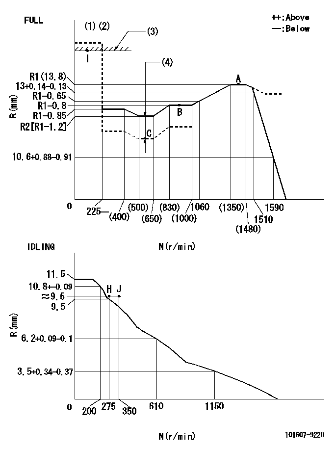
Governor adjustment

N:Pump speed
R:Rack position (mm)
(1)Torque cam stamping: T1
(2)Tolerance for racks not indicated: +-0.05mm.
(3)RACK LIMIT
(4)Boost compensator stroke: BCL
----------
T1=J98 BCL=1.05+-0.1mm
----------
----------
T1=J98 BCL=1.05+-0.1mm
----------
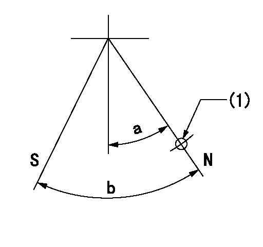
Speed control lever angle

F:Full speed
I:Idle
(1)Use the hole at R = aa
(2)Stopper bolt set position 'H'
----------
aa=100mm
----------
a=26.5deg+-5deg b=42deg+-3deg
----------
aa=100mm
----------
a=26.5deg+-5deg b=42deg+-3deg
Stop lever angle

N:Pump normal
S:Stop the pump.
(1)Use the hole at R = aa
----------
aa=36mm
----------
a=20deg+-5deg b=40deg+-5deg
----------
aa=36mm
----------
a=20deg+-5deg b=40deg+-5deg
Timing setting

(1)Pump vertical direction
(2)Coupling's key groove position at No 1 cylinder's beginning of injection
(3)-
(4)-
----------
----------
a=(30deg)
----------
----------
a=(30deg)
Information:
Illustration 1 g01046024
Engine with two turbochargers (1) Inlet valves (2) Exhaust valves (3) Inlet manifold (4) Exhaust manifold (5) Water inlet for the aftercooler (6) Water outlet for the aftercooler (7) Aftercooler (8) Air inlet (9) Exhaust outlet (10) Compressor (11) TurbineThe components of the air inlet and exhaust system control the quality of air and the amount of air that is available for combustion. The components of the air inlet and exhaust system are the following components:
Air cleaner
Turbocharger
Aftercooler
Cylinder head
Valves and valve system components
Piston and cylinder
Inlet manifold
Exhaust manifoldNote: The following description of the operation of the air inlet and exhaust system assumes that the engine is developing boost pressure. Inlet air passes through the air cleaner into the air inlet (8) of the turbocharger compressor wheel (10). The turbocharger will supply more volume of air into the engine. This compressing of the air is referred to as boost. The compressing of air causes the air temperature to rise to about 204 °C (400 °F). As the air flows through the aftercooler (7) the temperature of the compressed air lowers to about 46 °C (115 °F). Cooling of the inlet air causes the air to become more dense. This increases combustion efficiency and this increases horsepower output.From the aftercooler, air enters the inlet manifold (3). Air flow from the inlet manifold (3) into the cylinders is controlled by inlet valves (1). There are two inlet valves and two exhaust valves (2) for each cylinder. The inlet valves open at the top center position before the piston moves toward the bottom center position. This is called the inlet stroke. When the inlet valves open, cooled compressed air from the inlet port enters the cylinder. The inlet valves close as the piston reaches the bottom center position. The piston begins to travel back to the top center position on the compression stroke. The air in the cylinder is compressed to a very high temperature. When the piston is near the end of the compression stroke, fuel is injected into the cylinder and mixes with the air. This causes combustion to start in the cylinder. Once combustion starts, the combustion force pushes the piston toward the bottom center position. This is called the power stroke. The exhaust valves open when the piston moves toward the bottom center position and the exhaust gases are pushed through the exhaust port into exhaust manifold (4) as the piston travels toward top center on the exhaust stroke. The exhaust valves close and the cycle starts again. The complete cycle consists of four strokes:
Inlet
Compression
Power
ExhaustExhaust gases from the exhaust manifold (4) enter the turbine side of the turbocharger. The exhaust gas temperature causes the turbine wheel (11) in the turbocharger to turn. The turbine wheel is connected to the shaft that drives the compressor wheel. Exhaust gases from the turbine wheel exit the turbocharger (9) .Turbocharger
Illustration 2 g01361124
Water cooled turbocharger (8) Air inlet (9) Exhaust outlet (11) Exhaust inlet (12) Compressor housing (13) Compressor wheel (14) Bearing (15) Oil Inlet
