Information injection-pump assembly
ZEXEL
101607-6870
1016076870

Rating:
Cross reference number
ZEXEL
101607-6870
1016076870
Zexel num
Bosch num
Firm num
Name
101607-6870
INJECTION-PUMP ASSEMBLY
Calibration Data:
Adjustment conditions
Test oil
1404 Test oil ISO4113 or {SAEJ967d}
1404 Test oil ISO4113 or {SAEJ967d}
Test oil temperature
degC
40
40
45
Nozzle and nozzle holder
105780-8140
Bosch type code
EF8511/9A
Nozzle
105780-0000
Bosch type code
DN12SD12T
Nozzle holder
105780-2080
Bosch type code
EF8511/9
Opening pressure
MPa
17.2
Opening pressure
kgf/cm2
175
Injection pipe
Outer diameter - inner diameter - length (mm) mm 6-2-600
Outer diameter - inner diameter - length (mm) mm 6-2-600
Overflow valve
131424-8420
Overflow valve opening pressure
kPa
255
221
289
Overflow valve opening pressure
kgf/cm2
2.6
2.25
2.95
Tester oil delivery pressure
kPa
157
157
157
Tester oil delivery pressure
kgf/cm2
1.6
1.6
1.6
Direction of rotation (viewed from drive side)
Left L
Left L
Injection timing adjustment
Direction of rotation (viewed from drive side)
Left L
Left L
Injection order
1-5-3-6-
2-4
Pre-stroke
mm
3.2
3.15
3.25
Beginning of injection position
Governor side NO.1
Governor side NO.1
Difference between angles 1
Cal 1-5 deg. 60 59.5 60.5
Cal 1-5 deg. 60 59.5 60.5
Difference between angles 2
Cal 1-3 deg. 120 119.5 120.5
Cal 1-3 deg. 120 119.5 120.5
Difference between angles 3
Cal 1-6 deg. 180 179.5 180.5
Cal 1-6 deg. 180 179.5 180.5
Difference between angles 4
Cyl.1-2 deg. 240 239.5 240.5
Cyl.1-2 deg. 240 239.5 240.5
Difference between angles 5
Cal 1-4 deg. 300 299.5 300.5
Cal 1-4 deg. 300 299.5 300.5
Injection quantity adjustment
Adjusting point
-
Rack position
11.9
Pump speed
r/min
850
850
850
Each cylinder's injection qty
mm3/st.
81.5
79.1
83.9
Basic
*
Fixing the rack
*
Standard for adjustment of the maximum variation between cylinders
*
Injection quantity adjustment_02
Adjusting point
Z
Rack position
9.5+-0.5
Pump speed
r/min
700
700
700
Each cylinder's injection qty
mm3/st.
10.8
9.2
12.4
Fixing the rack
*
Standard for adjustment of the maximum variation between cylinders
*
Injection quantity adjustment_03
Adjusting point
A
Rack position
R1(11.9)
Pump speed
r/min
850
850
850
Average injection quantity
mm3/st.
81.5
80.5
82.5
Basic
*
Fixing the lever
*
Injection quantity adjustment_04
Adjusting point
B
Rack position
R1+0.25
Pump speed
r/min
1450
1450
1450
Average injection quantity
mm3/st.
85.5
81.5
89.5
Fixing the lever
*
Injection quantity adjustment_05
Adjusting point
C
Rack position
R1-0.4
Pump speed
r/min
500
500
500
Average injection quantity
mm3/st.
71
67
75
Fixing the lever
*
Injection quantity adjustment_06
Adjusting point
I
Rack position
-
Pump speed
r/min
100
100
100
Average injection quantity
mm3/st.
91
81
101
Fixing the lever
*
Rack limit
*
Timer adjustment
Pump speed
r/min
950--
Advance angle
deg.
0
0
0
Remarks
Start
Start
Timer adjustment_02
Pump speed
r/min
900
Advance angle
deg.
0.5
Timer adjustment_03
Pump speed
r/min
-
Advance angle
deg.
1
0.5
1.5
Remarks
Measure the actual speed.
Measure the actual speed.
Timer adjustment_04
Pump speed
r/min
1100
Advance angle
deg.
1
0.5
1.5
Timer adjustment_05
Pump speed
r/min
1400
Advance angle
deg.
7
6.5
7.5
Remarks
Finish
Finish
Test data Ex:
Governor adjustment

N:Pump speed
R:Rack position (mm)
(1)Torque cam stamping: T1
(2)Tolerance for racks not indicated: +-0.05mm.
(3)RACK LIMIT
----------
T1=J70
----------
----------
T1=J70
----------
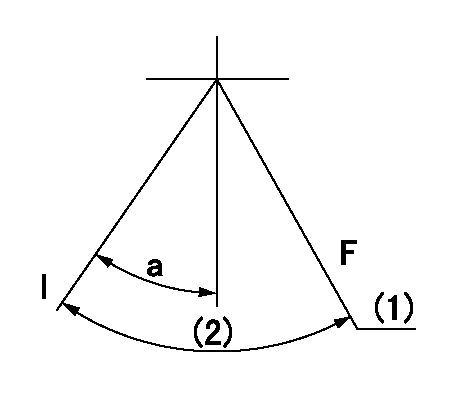
Speed control lever angle

F:Full speed
I:Idle
(1)Stopper bolt set position 'H'
----------
----------
a=10deg+-5deg b=(47.5deg)+-3deg
----------
----------
a=10deg+-5deg b=(47.5deg)+-3deg
Stop lever angle

N:Engine manufacturer's normal use
S:Stop the pump.
(1)Set the stopper bolt at pump speed = aa and rack position = bb (non-injection rack position). Confirm non-injection.
(2)After setting the stopper bolt, confirm non-injection at speed cc. Rack position = dd (non-injection rack position).
(3)Rack position = approximately ee.
(4)Free (at delivery)
----------
aa=1450r/min bb=7.2-0.5mm cc=275r/min dd=(8.8)mm ee=15mm
----------
a=36.5deg+-5deg b=(25deg) c=13deg+-5deg
----------
aa=1450r/min bb=7.2-0.5mm cc=275r/min dd=(8.8)mm ee=15mm
----------
a=36.5deg+-5deg b=(25deg) c=13deg+-5deg
0000001201
F:At operation, hold it in the full speed position.
I:Idle
(1)At rack position aa and pump speed bb, set the stopper bolt. (After setting it, apply red paint.)
(2)Actual measurement
----------
aa=9.9+-0.1mm bb=1575r/min
----------
a=15deg+-5deg
----------
aa=9.9+-0.1mm bb=1575r/min
----------
a=15deg+-5deg
Timing setting

(1)Pump vertical direction
(2)Position of timer's tooth at No 1 cylinder's beginning of injection
(3)B.T.D.C.: aa
(4)-
----------
aa=7deg
----------
a=(3deg)
----------
aa=7deg
----------
a=(3deg)
Information:
Lubricant Viscosity Recommendations for Direct Injection (DI) and Precombustion Chamber (PC) engines
Refer to the minimum temperature in table 1 in order to determine the required oil viscosity for starting a cold engine. Refer to the maximum temperature in order to select the oil viscosity for engine operation at the highest ambient temperature that is anticipated.Refer to this Special Publication, "General Information for Lubricants" article for important lubricant information.Supplemental heat is recommended for cold-soaked starts below the minimum ambient temperature. Supplemental heat may be required for cold-soaked starts that are above the minimum temperature that is stated, depending on the parasitic load and other factors. Cold-soaked starts occur when the engine has not been operated for a time, allowing the oil to become more viscous in cooler ambient temperatures.For oil recommendations for Tier 4 EPA certified engines, EU stage IIIB and IV type approved engines, and Japan Step IV approved engines refer to the Special Publication, "Engine Oil" section. Refer to this Special Publication, "Lubricant Information" section for a list of all Cat engine oils.Note: Use the highest oil viscosity that is available to meet the requirement for the temperature at start-up.If ambient temperature conditions at engine start-up require the use of multigrade SAE 0W oil, SAE 0W-40 viscosity grade is preferred over SAE 0W-30.Note: Cat offers Special Application Engine Oil (SAEO), API CF oil of SAE 30 and SAE 40 viscosity grades. These oils are recommended for use in 3116 and 3126 marine engines.Note: 10W-30 is the preferred viscosity grade for the 3116, 3126, C7, C-9, and C9 diesel engines when the ambient temperature is above −18° C (0° F) and below 40° C (104° F).Note: C175 Series diesel engines require the use of multigrade SAE 40 oil: SAE 0W-40, SAE 5W-40, SAE 10W-40, or SAE 15W-40. In ambient temperatures of −9.5° C (15° F) or above, SAE 15W-40 is the preferred oil viscosity grade.If ambient temperature conditions at engine start-up require the use of multigrade SAE 0W oil, SAE 0W-40 viscosity grade is preferred over SAE 0W-30.Refer to table 1 and associated footnotes for guidance on selecting the proper oil viscosity grade for various ambient temperatures.
Table 1
Lubricant Viscosities for Ambient Temperatures for Cat Diesel Engines(1)(2)
Engine Type Oil Type and Performance Requirements Viscosity Grade °C °F
Min Max Min Max
Direct Injection (DI) and Pre Combustion (PC) Cat Cold-Weather DEO-ULS (API CK-4) SAE 0W-40 −40 40 −40 104
Cat DEO-ULS SYN (API CK-4) SAE 5W-40 −30 50 −22 122
Cat DEO-ULS (API CK-4)
Cat DEO (API CPI-4/CPI-4 PLUS) SAE 10W-30 −18 40 0 104
SAE 15W-40 −10 50 14 122
Pre Combustion (PC) only Cat PCO SAE 40 5 50 41 122
(1) Refer to Special Publication, SEBU6251, "Engine Oil", for information on the recommended and required engine oils for Tier 4 emissions certified engines.
(2) Commercial oils of viscosity grades that are not included in this table may be used if they are per Cat ECF specifications. Refer to the “Cat Engine Crankcase Fluids (ECF) Definitions” table in this Special Publication, "Engine Oil" for more information. Commercial oils
Have questions with 101607-6870?
Group cross 101607-6870 ZEXEL
101607-6870
INJECTION-PUMP ASSEMBLY