Information injection-pump assembly
ZEXEL
101607-6820
1016076820

Rating:
Cross reference number
ZEXEL
101607-6820
1016076820
Zexel num
Bosch num
Firm num
Name
101607-6820
INJECTION-PUMP ASSEMBLY
Calibration Data:
Adjustment conditions
Test oil
1404 Test oil ISO4113 or {SAEJ967d}
1404 Test oil ISO4113 or {SAEJ967d}
Test oil temperature
degC
40
40
45
Nozzle and nozzle holder
105780-8140
Bosch type code
EF8511/9A
Nozzle
105780-0000
Bosch type code
DN12SD12T
Nozzle holder
105780-2080
Bosch type code
EF8511/9
Opening pressure
MPa
17.2
Opening pressure
kgf/cm2
175
Injection pipe
Outer diameter - inner diameter - length (mm) mm 6-2-600
Outer diameter - inner diameter - length (mm) mm 6-2-600
Overflow valve
131424-8420
Overflow valve opening pressure
kPa
255
221
289
Overflow valve opening pressure
kgf/cm2
2.6
2.25
2.95
Tester oil delivery pressure
kPa
157
157
157
Tester oil delivery pressure
kgf/cm2
1.6
1.6
1.6
Direction of rotation (viewed from drive side)
Left L
Left L
Injection timing adjustment
Direction of rotation (viewed from drive side)
Left L
Left L
Injection order
1-5-3-6-
2-4
Pre-stroke
mm
3.2
3.15
3.25
Beginning of injection position
Governor side NO.1
Governor side NO.1
Difference between angles 1
Cal 1-5 deg. 60 59.5 60.5
Cal 1-5 deg. 60 59.5 60.5
Difference between angles 2
Cal 1-3 deg. 120 119.5 120.5
Cal 1-3 deg. 120 119.5 120.5
Difference between angles 3
Cal 1-6 deg. 180 179.5 180.5
Cal 1-6 deg. 180 179.5 180.5
Difference between angles 4
Cyl.1-2 deg. 240 239.5 240.5
Cyl.1-2 deg. 240 239.5 240.5
Difference between angles 5
Cal 1-4 deg. 300 299.5 300.5
Cal 1-4 deg. 300 299.5 300.5
Injection quantity adjustment
Adjusting point
-
Rack position
11.9
Pump speed
r/min
850
850
850
Each cylinder's injection qty
mm3/st.
81.5
79.1
83.9
Basic
*
Fixing the rack
*
Standard for adjustment of the maximum variation between cylinders
*
Injection quantity adjustment_02
Adjusting point
Z
Rack position
9.5+-0.5
Pump speed
r/min
700
700
700
Each cylinder's injection qty
mm3/st.
10.8
9.2
12.4
Fixing the rack
*
Standard for adjustment of the maximum variation between cylinders
*
Injection quantity adjustment_03
Adjusting point
A
Rack position
R1(11.9)
Pump speed
r/min
850
850
850
Average injection quantity
mm3/st.
81.5
80.5
82.5
Basic
*
Fixing the lever
*
Injection quantity adjustment_04
Adjusting point
B
Rack position
R1+0.25
Pump speed
r/min
1450
1450
1450
Average injection quantity
mm3/st.
85.5
81.5
89.5
Fixing the lever
*
Injection quantity adjustment_05
Adjusting point
C
Rack position
R1-0.4
Pump speed
r/min
500
500
500
Average injection quantity
mm3/st.
71
67
75
Fixing the lever
*
Injection quantity adjustment_06
Adjusting point
I
Rack position
-
Pump speed
r/min
100
100
100
Average injection quantity
mm3/st.
91
81
101
Fixing the lever
*
Rack limit
*
Timer adjustment
Pump speed
r/min
950--
Advance angle
deg.
0
0
0
Remarks
Start
Start
Timer adjustment_02
Pump speed
r/min
900
Advance angle
deg.
0.5
Timer adjustment_03
Pump speed
r/min
-
Advance angle
deg.
1
0.5
1.5
Remarks
Measure the actual speed.
Measure the actual speed.
Timer adjustment_04
Pump speed
r/min
1100
Advance angle
deg.
1
0.5
1.5
Timer adjustment_05
Pump speed
r/min
1400
Advance angle
deg.
7
6.5
7.5
Remarks
Finish
Finish
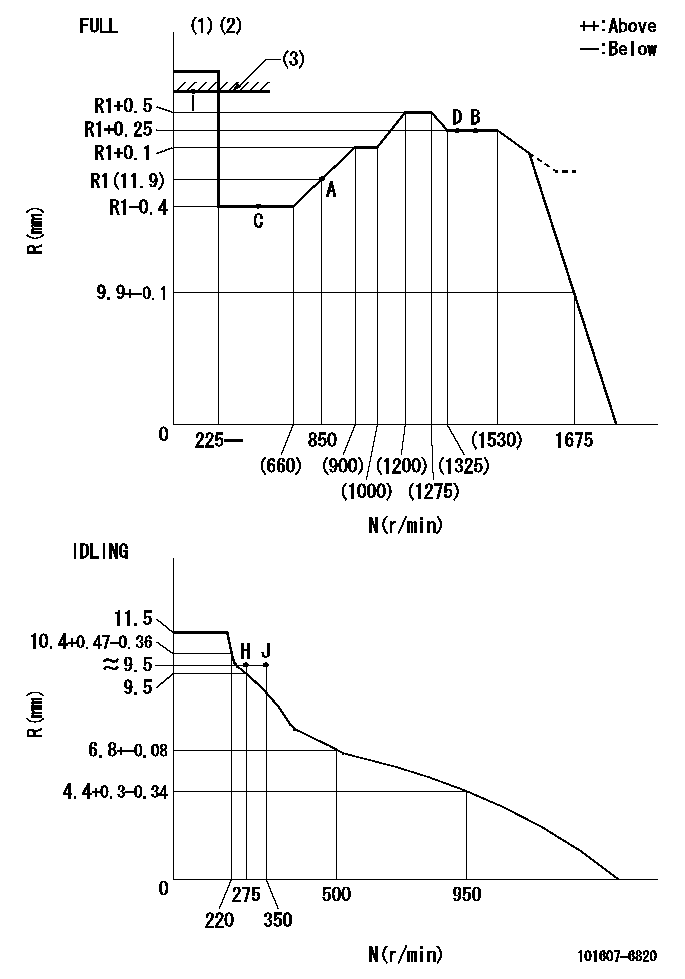
Test data Ex:
Governor adjustment

N:Pump speed
R:Rack position (mm)
(1)Torque cam stamping: T1
(2)Tolerance for racks not indicated: +-0.05mm.
(3)RACK LIMIT
----------
T1=J70
----------
----------
T1=J70
----------
Speed control lever angle

F:Full speed
I:Idle
(1)Stopper bolt set position 'H'
----------
----------
a=24deg+-5deg b=(47.5deg)+-3deg
----------
----------
a=24deg+-5deg b=(47.5deg)+-3deg
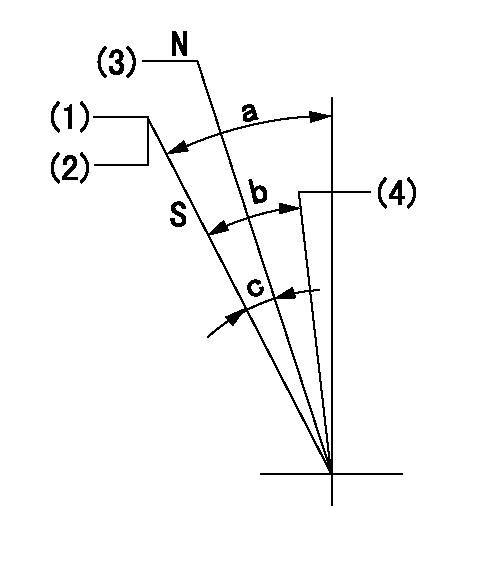
Stop lever angle

N:Engine manufacturer's normal use
S:Stop the pump.
(1)Set the stopper bolt at pump speed = aa and rack position = bb (non-injection rack position). Confirm non-injection.
(2)After setting the stopper bolt, confirm non-injection at speed cc. Rack position = dd (non-injection rack position).
(3)Rack position = approximately ee.
(4)Free (at delivery)
----------
aa=1450r/min bb=7.2-0.5mm cc=275r/min dd=(8.8)mm ee=15mm
----------
a=36.5deg+-5deg b=(25deg) c=13deg+-5deg
----------
aa=1450r/min bb=7.2-0.5mm cc=275r/min dd=(8.8)mm ee=15mm
----------
a=36.5deg+-5deg b=(25deg) c=13deg+-5deg
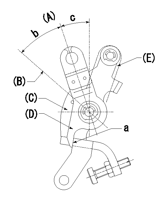
0000001501 LEVER

(A) Idle
(B) Full speed
(C) Base lever
(D) Accelerator lever
(E) Accelerator lever delivery position
1. Measure speed lever angle
(1)Measure the angle when the accelerator lever (D) contacted the base lever (C) at a.
----------
----------
b=(47.5deg)+-3deg c=24deg+-5deg
----------
----------
b=(47.5deg)+-3deg c=24deg+-5deg
Timing setting LEVER

(1)Pump vertical direction
(2)Position of timer's tooth at No 1 cylinder's beginning of injection
(3)B.T.D.C.: aa
(4)-
----------
aa=7deg
----------
a=(3deg)
----------
aa=7deg
----------
a=(3deg)
Information:
The Caterpillar Electronic Technician (ET)
Illustration 1 g00777826
The Caterpillar Electronic Technician (ET) is a software program that is used to access data. The service technician can use the Caterpillar Electronic Technician in order to perform maintenance work on the machine. Some of the options that are available with the Caterpillar Electronic Technician are listed below:
View Diagnostic codes. See Troubleshooting, "Using the Caterpillar Electronic Technician to Determine Diagnostic Codes".
View the status of parameters.
Clear active diagnostic codes and clear logged diagnostic codes
Perform calibration of machine systems.
Program the ECM (Flash). This is done with the "WINflash" program. See Testing and Adjusting, "Electronic Control Module (ECM) - Flash Program".
Print reports.The following list contains some of the diagnostic functions and programming functions that are performed by the service tools.
The failures of the ECM system are displayed.
The status of most of the inputs and the outputs are displayed.
The settings for the ECM are displayed.
Display the status of the input and output parameters in real time.
Display the clock hour of the internal diagnostic clock.
The number of occurrences and the clock hour of the first occurrence and the last occurrence is displayed for each logged diagnostic code.
The definition for each logged diagnostic code and each event is displayed.
Load new FLASH software.See Troubleshooting, "Diagnostic Code List" for the list of diagnostic codes for the ECM.See Troubleshooting, "Using the Caterpillar Electronic Technician to Determine Diagnostic Codes". Diagnostic information is accessed with the following drop down menus:
Active diagnostic codes
Logged diagnostic codesSensor Diagnostics
The following tables show the conditions that the diagnostic codes are set for each sensor. If any of the diagnostic codes are active, the System Problem for the LED will be turned on. During the Debounce time, the affected parameter will remain at the last good value. After the Debounce time, the affected parameter will be set to the default value. Refer to Table 1.
Table 1
Sensor Sample Period (mS) Too Low Too High Defaults
Inlet Pressure (gauge) Code Condition Debounce Code Condition Debounce NA
1 81-4 Input < 0.5 VDC 5 sec on
5 sec off 81-3 Input greater than 4.5 VDC 5 sec on
5 sec off NA
Exhaust Temperature 1 535-4 Input < 1.5 VDC 5 sec on
5 sec off 535-3 Input greater than 4.0 VDC 5 sec on
5 sec off NA Temperature Sensor
Table 2 refers to the properties of the temperature sensor.
Table 2
Function Part Number Measure Range Output Accuracy Power Supply Sensor Mounting Mating
Exhaust Temperature 280-3921
50 °C (122 °F)to
850 °C (1562 °F) N/A
500° 5°C (932° 9°F) to
850° 5°C (1562° 9°F) 5V (+/- 0.5) Thread Size: M14 X 1.5
Probe Length:
70 mm (2.7559 inch) from flange to tip 230-5008 Connector Plug As Pressure Sensor
Table 3
Function PN Max Pressure Measure Burst Pressure Power
Have questions with 101607-6820?
Group cross 101607-6820 ZEXEL
101607-6820
INJECTION-PUMP ASSEMBLY