Information injection-pump assembly
ZEXEL
101607-6706
1016076706

Rating:
Service parts 101607-6706 INJECTION-PUMP ASSEMBLY:
1.
_
6.
COUPLING PLATE
7.
COUPLING PLATE
8.
_
9.
_
11.
Nozzle and Holder
ME075761
12.
Open Pre:MPa(Kqf/cm2)
15.7{160}/21.6{220}
14.
NOZZLE

Include in #1:
101607-6706
as INJECTION-PUMP ASSEMBLY
Include in #2:
104746-5030
as _
Cross reference number
ZEXEL
101607-6706
1016076706
Zexel num
Bosch num
Firm num
Name
101607-6706
INJECTION-PUMP ASSEMBLY
14BF PE6AD PE
14BF PE6AD PE
Calibration Data:
Adjustment conditions
Test oil
1404 Test oil ISO4113 or {SAEJ967d}
1404 Test oil ISO4113 or {SAEJ967d}
Test oil temperature
degC
40
40
45
Nozzle and nozzle holder
105780-8140
Bosch type code
EF8511/9A
Nozzle
105780-0000
Bosch type code
DN12SD12T
Nozzle holder
105780-2080
Bosch type code
EF8511/9
Opening pressure
MPa
17.2
Opening pressure
kgf/cm2
175
Injection pipe
Outer diameter - inner diameter - length (mm) mm 6-2-600
Outer diameter - inner diameter - length (mm) mm 6-2-600
Overflow valve
131424-8420
Overflow valve opening pressure
kPa
255
221
289
Overflow valve opening pressure
kgf/cm2
2.6
2.25
2.95
Tester oil delivery pressure
kPa
157
157
157
Tester oil delivery pressure
kgf/cm2
1.6
1.6
1.6
Direction of rotation (viewed from drive side)
Left L
Left L
Injection timing adjustment
Direction of rotation (viewed from drive side)
Left L
Left L
Injection order
1-5-3-6-
2-4
Pre-stroke
mm
3.2
3.15
3.25
Beginning of injection position
Governor side NO.1
Governor side NO.1
Difference between angles 1
Cal 1-5 deg. 60 59.5 60.5
Cal 1-5 deg. 60 59.5 60.5
Difference between angles 2
Cal 1-3 deg. 120 119.5 120.5
Cal 1-3 deg. 120 119.5 120.5
Difference between angles 3
Cal 1-6 deg. 180 179.5 180.5
Cal 1-6 deg. 180 179.5 180.5
Difference between angles 4
Cyl.1-2 deg. 240 239.5 240.5
Cyl.1-2 deg. 240 239.5 240.5
Difference between angles 5
Cal 1-4 deg. 300 299.5 300.5
Cal 1-4 deg. 300 299.5 300.5
Injection quantity adjustment
Adjusting point
-
Rack position
11.8
Pump speed
r/min
850
850
850
Each cylinder's injection qty
mm3/st.
80
77.6
82.4
Basic
*
Fixing the rack
*
Standard for adjustment of the maximum variation between cylinders
*
Injection quantity adjustment_02
Adjusting point
Z
Rack position
9.5+-0.5
Pump speed
r/min
600
600
600
Each cylinder's injection qty
mm3/st.
10.8
9.2
12.4
Fixing the rack
*
Standard for adjustment of the maximum variation between cylinders
*
Injection quantity adjustment_03
Adjusting point
A
Rack position
R1(11.8)
Pump speed
r/min
850
850
850
Average injection quantity
mm3/st.
80
79
81
Basic
*
Fixing the lever
*
Injection quantity adjustment_04
Adjusting point
B
Rack position
R1+0.35
Pump speed
r/min
1450
1450
1450
Average injection quantity
mm3/st.
85
81
89
Fixing the lever
*
Injection quantity adjustment_05
Adjusting point
C
Rack position
R1-0.4
Pump speed
r/min
500
500
500
Average injection quantity
mm3/st.
58.5
54.5
62.5
Fixing the lever
*
Injection quantity adjustment_06
Adjusting point
I
Rack position
-
Pump speed
r/min
100
100
100
Average injection quantity
mm3/st.
95
85
105
Fixing the lever
*
Rack limit
*
Timer adjustment
Pump speed
r/min
950--
Advance angle
deg.
0
0
0
Remarks
Start
Start
Timer adjustment_02
Pump speed
r/min
900
Advance angle
deg.
0.5
Timer adjustment_03
Pump speed
r/min
-
Advance angle
deg.
1
0.5
1.5
Remarks
Measure the actual speed.
Measure the actual speed.
Timer adjustment_04
Pump speed
r/min
1100
Advance angle
deg.
1
0.5
1.5
Timer adjustment_05
Pump speed
r/min
1400
Advance angle
deg.
7
6.5
7.5
Remarks
Finish
Finish
Test data Ex:
Governor adjustment

N:Pump speed
R:Rack position (mm)
(1)Torque cam stamping: T1
(2)Tolerance for racks not indicated: +-0.05mm.
(3)RACK LIMIT
----------
T1=K60
----------
----------
T1=K60
----------
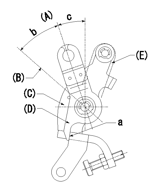
Speed control lever angle

F:Full speed
I:Idle
(1)Stopper bolt set position 'H'
----------
----------
a=18.5deg+-5deg b=42deg+-3deg
----------
----------
a=18.5deg+-5deg b=42deg+-3deg
Stop lever angle

N:Engine manufacturer's normal use
S:Stop the pump.
(1)Set the stopper bolt so that speed = aa and rack position = bb and confirm non-injection.
(2)After setting the stopper bolt, confirm non-injection at speed cc. Rack position = dd (non-injection rack position).
(3)Rack position = approximately ee (speed lever full, speed = ff).
(4)Free (at delivery)
----------
aa=1450r/min bb=7.2-0.5mm cc=275r/min dd=(8.8)mm ee=15mm ff=0r/min
----------
a=36.5deg+-5deg b=(25deg) c=13deg+-5deg
----------
aa=1450r/min bb=7.2-0.5mm cc=275r/min dd=(8.8)mm ee=15mm ff=0r/min
----------
a=36.5deg+-5deg b=(25deg) c=13deg+-5deg
0000001501 MICRO SWITCH
Adjust the bolt to obtain the following lever position when the micro-switch is ON.
1. Microswitch adjustment (OPEN type)
Confirm with the lever angle at full.
(1)Speed N1
(2)Rack position Ra
2. Idle side microswitch adjustment (OPEN type)
Confirm with the lever angle at idle.
(1)Speed N2
(2)Rack position Rb
----------
N1=1675r/min Ra=8.5+-0.1mm N2=275r/min Rb=9.7+-0.1mm
----------
----------
N1=1675r/min Ra=8.5+-0.1mm N2=275r/min Rb=9.7+-0.1mm
----------
0000001601 RACK SENSOR

V1:Supply voltage
V2f:Full side output voltage
V2i:Idle side output voltage
(A) Black
(B) Yellow
(C) Red
(D) Trimmer
(E): Shaft
(F) Nut
(G) Load lever
1. Load sensor adjustment
(1)Connect as shown in the above diagram and apply supply voltage V1.
(2)Hold the load lever (G) against the full side.
(3)Turn the shaft so that the voltage between (A) and (B) is V2.
(4)Hold the load lever (G) against the idle side.
(5)Adjust (D) so that the voltage between (A) and (B) is V2i.
(6)Repeat the above adjustments.
(7)Tighten the nut (F) at the point satisfying the standards.
(8)Hold the load lever against the full side stopper and the idle side stopper.
(9)At this time, confirm that the full side output voltage is V2f and the idle side output voltage is V2i.
----------
V1=3.57+-0.02V V2f=1+0.1V V2i=3+0.05V
----------
----------
V1=3.57+-0.02V V2f=1+0.1V V2i=3+0.05V
----------
0000001701 LEVER
(A) Idle
(B) Full speed
(C) Base lever
(D) Accelerator lever
(E) Accelerator lever delivery position
1. Measure speed lever angle
(1)Measure the angle when the accelerator lever (D) contacted the base lever (C) at a.
----------
----------
b=42deg+-3deg c=18.5deg+-5deg
----------
----------
b=42deg+-3deg c=18.5deg+-5deg
Timing setting

(1)Pump vertical direction
(2)Position of timer's tooth at No 1 cylinder's beginning of injection
(3)B.T.D.C.: aa
(4)-
----------
aa=7deg
----------
a=(4deg)
----------
aa=7deg
----------
a=(4deg)
Information:
Table 1
S O S Oil Analysis Guidelines
Test Parameter Guideline
Oxidation (1)
Soot (1)
Sulfation (1)
Wear Metals Trend Analysis and Cat Wear Table (1) norms
Water 0.5% maximum
Glycol 0%
Fuel Dilution Based on viscosity (1) and GC (2) fuel dilution in excess of 4%
Viscosity "ASTM D445" measured at 100° C (212° F) +/-3 centistokes (cSt) change from new oil viscosity.
( 1 ) Acceptable values for these parameters are proprietary to the S O S oil analysis program.
( 2 ) Gas ChromatographConsult your Caterpillar dealer for complete information and assistance about the S O S oil analysis program.Obtaining S O S Oil Samples
Before you obtain an S O S oil sample, operate the engine until the oil is warm and the oil is well circulated. Then obtain the S O S oil sample.In order to obtain a good oil sample, do not take the oil sample from the drain stream. The drain stream method can allow a stream of dirty oil from the bottom of the compartment to contaminate the sample. Likewise, never dip an oil sample from an oil container or pour a sample from a used filter.There are two acceptable ways to obtain S O S oil samples. The following methods are listed in the order that is preferred:
Use an in-line sampling valve on the pressurized oil manifold.
Use a sampling gun (vacuum pump) that is inserted into the sump.Use of the in-line sampling valve is the preferred method. This method provides samples that are less likely to be contaminated. In order to obtain an oil sample from the engine, it may be necessary to increase the engine's speed. Normally, the oil sample is taken at low idle. If the flow rate is too low, increase engine speed to high idle in order to obtain the oil sample.
Do not use the same vacuum sampling pump for extracting oil samples that is used for extracting coolant samples.A small residue of either type sample may remain in the pump and may cause a false positive analysis for the sample being taken.Always use a separate pump for oil sampling and a separate pump for coolant sampling.Failure to do so may cause a false analysis which could lead to customer and dealer concerns.
Oil Sampling Interval
Take the oil samples as close as possible to the standard intervals. In order to receive the full value from S O S oil analysis, you must establish a consistent trend of data. In order to establish pertinent history of data, perform consistent oil samplings that are evenly spaced.
Table 2
Compartment Engine
Recommended Sampling Interval
24140 kilometers (15000 miles)
(1) (2)
Sampling Valve Yes
Oil Type DEO, DEO-ULS
Recommended Oil Change Interval (3)
( 1 ) Under certain conditions, the Caterpillar dealer or the Operation and Maintenance Manual may allow a longer
Have questions with 101607-6706?
Group cross 101607-6706 ZEXEL
101607-6706
INJECTION-PUMP ASSEMBLY