Information injection-pump assembly
ZEXEL
101607-6626
1016076626

Rating:
Service parts 101607-6626 INJECTION-PUMP ASSEMBLY:
1.
_
6.
COUPLING PLATE
7.
COUPLING PLATE
8.
_
9.
_
11.
Nozzle and Holder
ME075405
12.
Open Pre:MPa(Kqf/cm2)
15.7{160}/21.6{220}
15.
NOZZLE SET
Cross reference number
ZEXEL
101607-6626
1016076626
Zexel num
Bosch num
Firm num
Name
101607-6626
INJECTION-PUMP ASSEMBLY
Calibration Data:
Adjustment conditions
Test oil
1404 Test oil ISO4113 or {SAEJ967d}
1404 Test oil ISO4113 or {SAEJ967d}
Test oil temperature
degC
40
40
45
Nozzle and nozzle holder
105780-8140
Bosch type code
EF8511/9A
Nozzle
105780-0000
Bosch type code
DN12SD12T
Nozzle holder
105780-2080
Bosch type code
EF8511/9
Opening pressure
MPa
17.2
Opening pressure
kgf/cm2
175
Injection pipe
Outer diameter - inner diameter - length (mm) mm 6-2-600
Outer diameter - inner diameter - length (mm) mm 6-2-600
Overflow valve
131424-8420
Overflow valve opening pressure
kPa
255
221
289
Overflow valve opening pressure
kgf/cm2
2.6
2.25
2.95
Tester oil delivery pressure
kPa
157
157
157
Tester oil delivery pressure
kgf/cm2
1.6
1.6
1.6
Direction of rotation (viewed from drive side)
Left L
Left L
Injection timing adjustment
Direction of rotation (viewed from drive side)
Left L
Left L
Injection order
1-5-3-6-
2-4
Pre-stroke
mm
3.2
3.15
3.25
Beginning of injection position
Governor side NO.1
Governor side NO.1
Difference between angles 1
Cal 1-5 deg. 60 59.5 60.5
Cal 1-5 deg. 60 59.5 60.5
Difference between angles 2
Cal 1-3 deg. 120 119.5 120.5
Cal 1-3 deg. 120 119.5 120.5
Difference between angles 3
Cal 1-6 deg. 180 179.5 180.5
Cal 1-6 deg. 180 179.5 180.5
Difference between angles 4
Cyl.1-2 deg. 240 239.5 240.5
Cyl.1-2 deg. 240 239.5 240.5
Difference between angles 5
Cal 1-4 deg. 300 299.5 300.5
Cal 1-4 deg. 300 299.5 300.5
Injection quantity adjustment
Adjusting point
-
Rack position
11.7
Pump speed
r/min
850
850
850
Each cylinder's injection qty
mm3/st.
78
75.7
80.3
Basic
*
Fixing the rack
*
Standard for adjustment of the maximum variation between cylinders
*
Injection quantity adjustment_02
Adjusting point
Z
Rack position
10+-0.5
Pump speed
r/min
480
480
480
Each cylinder's injection qty
mm3/st.
21.8
18.5
25.1
Fixing the rack
*
Standard for adjustment of the maximum variation between cylinders
*
Injection quantity adjustment_03
Adjusting point
A
Rack position
R1(11.7)
Pump speed
r/min
850
850
850
Average injection quantity
mm3/st.
78
77
79
Basic
*
Fixing the lever
*
Injection quantity adjustment_04
Adjusting point
B
Rack position
R1+0.25
Pump speed
r/min
1450
1450
1450
Average injection quantity
mm3/st.
82.5
78.5
86.5
Fixing the lever
*
Injection quantity adjustment_05
Adjusting point
C
Rack position
R1-0.5
Pump speed
r/min
500
500
500
Average injection quantity
mm3/st.
52.5
48.5
56.5
Fixing the lever
*
Injection quantity adjustment_06
Adjusting point
I
Rack position
-
Pump speed
r/min
100
100
100
Average injection quantity
mm3/st.
115
115
135
Fixing the lever
*
Rack limit
*
Timer adjustment
Pump speed
r/min
950--
Advance angle
deg.
0
0
0
Remarks
Start
Start
Timer adjustment_02
Pump speed
r/min
900
Advance angle
deg.
0.5
Timer adjustment_03
Pump speed
r/min
-
Advance angle
deg.
1
0.5
1.5
Remarks
Measure the actual speed.
Measure the actual speed.
Timer adjustment_04
Pump speed
r/min
1200
Advance angle
deg.
1
0.5
1.5
Timer adjustment_05
Pump speed
r/min
1450
Advance angle
deg.
7
6.5
7.5
Remarks
Finish
Finish
Test data Ex:
Governor adjustment

N:Pump speed
R:Rack position (mm)
(1)Torque cam stamping: T1
(2)Tolerance for racks not indicated: +-0.05mm.
(3)RACK LIMIT
----------
T1=K59
----------
----------
T1=K59
----------
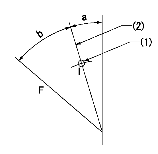
Speed control lever angle

F:Full speed
I:Idle
(1)Use the hole at R = aa
(2)Stopper bolt set position 'H'
----------
aa=40mm
----------
a=21deg+-5deg b=38deg+-3deg
----------
aa=40mm
----------
a=21deg+-5deg b=38deg+-3deg
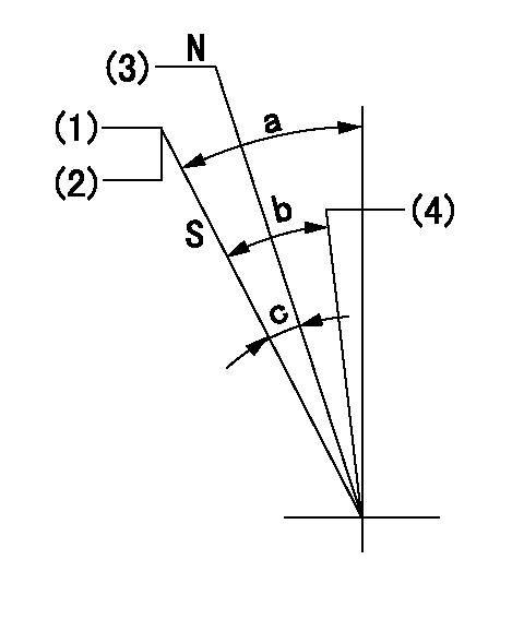
Stop lever angle

N:Engine manufacturer's normal use
S:Stop the pump.
(1)Set the stopper bolt at pump speed = aa and rack position = bb (non-injection rack position). Confirm non-injection.
(2)After setting the stopper bolt, confirm non-injection at speed cc. Rack position = dd (non-injection rack position).
(3)Rack position = approximately ee (speed lever full, speed = ff).
(4)Free (at delivery)
----------
aa=1450r/min bb=7.2-0.5mm cc=275r/min dd=(8.8)mm ee=15mm ff=0r/min
----------
a=36.5deg+-5deg b=(25deg) c=13deg+-5deg
----------
aa=1450r/min bb=7.2-0.5mm cc=275r/min dd=(8.8)mm ee=15mm ff=0r/min
----------
a=36.5deg+-5deg b=(25deg) c=13deg+-5deg
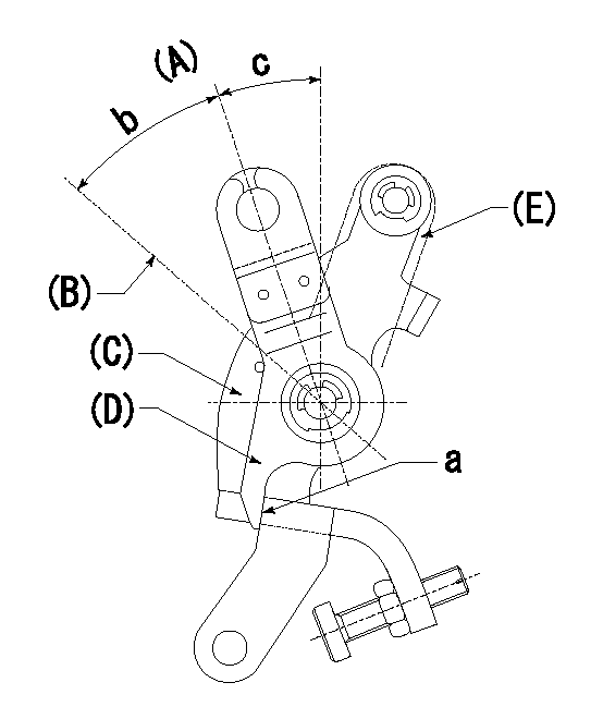
0000001501 LEVER

(A) Idle
(B) Full speed
(C) Base lever
(D) Accelerator lever
(E) Accelerator lever delivery position
1. Measure speed lever angle
(1)Measure the angle when the accelerator lever (D) contacted the base lever (C) at a.
----------
----------
b=38deg+-3deg c=21deg+-5deg
----------
----------
b=38deg+-3deg c=21deg+-5deg
Timing setting

(1)Pump vertical direction
(2)Position of timer's tooth at No 1 cylinder's beginning of injection
(3)B.T.D.C.: aa
(4)-
----------
aa=7deg
----------
a=(3deg)
----------
aa=7deg
----------
a=(3deg)
Information:
These recommendations are subject to change without notice. Consult your local Cat dealer for the most up to date recommendations.
Note: Non-Cat commercial greases are as a group second choice greases. Within this grouping of second choice greases there are tiered levels of performance.
Cat does not warrant the quality or performance of non-Cat fluids and greases.
Caterpillar provides a family of grease products that vary in performance from moderate to high performance. These greases service the entire line of Cat products in the wide variety of climates throughout the world. From this variety of Cat grease products, you can find a Cat grease that will meet or exceed the performance requirements for almost every machine that is produced by any Original Equipment Manufacturer (OEM), and for almost every machine application or equipment application.Before selecting a grease product, the performance requirements must be determined. Consult the grease recommendations in your Operation and Maintenance Manual. Also, consult your Cat dealer for a list of greases that have the performance specifications and the available container sizes.This grease chapter refers to NLGI of the grease products offered by Caterpillar. The National Lubricating Grease Institute (NLGI) classifies the greases per their consistency or hardness according to "ASTM D4950" and "SAE J310". The higher the NLGI value the more firm the grease. NLGI is an important classification for greases and it should be used along with other properties such as stability, corrosion resistance, viscosity, etc.Note: Always choose grease that meets or exceeds the recommendations that are specified by the equipment manufacturer for the application.Some work sites require the use of a single grease to fulfill the needs of all the equipment. Always choose a grease that meets or exceeds the requirements of the most demanding application. Remember that commercial products which barely meet the minimum performance requirements can be expected to produce the minimum life for the parts. It is not recommended to purchase grease products based on the lowest cost as the only consideration. Instead, use the grease that yields the lowest total operating cost. This cost should be based on an analysis that includes the improved product life, costs of parts, labor, downtime, and the cost of the amount of grease that is required.Note: Certain Cat grease products are formulated with Molybdenum disulfide (MoS2 or “Moly”). The Moly used in Cat greases is of a technical fine grade. This size meets the special requirements of some rolling element bearings, joints, and other moving components of tight clearances.Note: When the grease in a joint is changed from one type of grease to another or a grease from a different supplier is to be used, the general recommendation is to purge all of the old grease from the joint. Some greases are not chemically compatible. Consult your supplier in order to determine if the greases are compatible.If in doubt, Purge!Note: All Cat greases are “chemically” compatible with each other. Mixing of Cat greases will not result in an adverse chemical reaction. However, mixing of Cat greases
Have questions with 101607-6626?
Group cross 101607-6626 ZEXEL
101607-6626
INJECTION-PUMP ASSEMBLY