Information injection-pump assembly
BOSCH
9 400 615 709
9400615709
ZEXEL
101607-6520
1016076520
MITSUBISHI
ME077808
me077808

Rating:
Include in #1:
101402-7680
as _
Cross reference number
BOSCH
9 400 615 709
9400615709
ZEXEL
101607-6520
1016076520
MITSUBISHI
ME077808
me077808
Zexel num
Bosch num
Firm num
Name
101607-6520
9 400 615 709
ME077808 MITSUBISHI
INJECTION-PUMP ASSEMBLY
6D16 K
6D16 K
Calibration Data:
Adjustment conditions
Test oil
1404 Test oil ISO4113 or {SAEJ967d}
1404 Test oil ISO4113 or {SAEJ967d}
Test oil temperature
degC
40
40
45
Nozzle and nozzle holder
105780-8140
Bosch type code
EF8511/9A
Nozzle
105780-0000
Bosch type code
DN12SD12T
Nozzle holder
105780-2080
Bosch type code
EF8511/9
Opening pressure
MPa
17.2
Opening pressure
kgf/cm2
175
Injection pipe
Outer diameter - inner diameter - length (mm) mm 6-2-600
Outer diameter - inner diameter - length (mm) mm 6-2-600
Overflow valve
131424-8420
Overflow valve opening pressure
kPa
255
221
289
Overflow valve opening pressure
kgf/cm2
2.6
2.25
2.95
Tester oil delivery pressure
kPa
157
157
157
Tester oil delivery pressure
kgf/cm2
1.6
1.6
1.6
Direction of rotation (viewed from drive side)
Left L
Left L
Injection timing adjustment
Direction of rotation (viewed from drive side)
Left L
Left L
Injection order
1-5-3-6-
2-4
Pre-stroke
mm
3.2
3.15
3.25
Beginning of injection position
Governor side NO.1
Governor side NO.1
Difference between angles 1
Cal 1-5 deg. 60 59.5 60.5
Cal 1-5 deg. 60 59.5 60.5
Difference between angles 2
Cal 1-3 deg. 120 119.5 120.5
Cal 1-3 deg. 120 119.5 120.5
Difference between angles 3
Cal 1-6 deg. 180 179.5 180.5
Cal 1-6 deg. 180 179.5 180.5
Difference between angles 4
Cyl.1-2 deg. 240 239.5 240.5
Cyl.1-2 deg. 240 239.5 240.5
Difference between angles 5
Cal 1-4 deg. 300 299.5 300.5
Cal 1-4 deg. 300 299.5 300.5
Injection quantity adjustment
Adjusting point
-
Rack position
11.7
Pump speed
r/min
850
850
850
Each cylinder's injection qty
mm3/st.
77.4
75.1
79.7
Basic
*
Fixing the rack
*
Standard for adjustment of the maximum variation between cylinders
*
Injection quantity adjustment_02
Adjusting point
Z
Rack position
9.5+-0.5
Pump speed
r/min
800
800
800
Each cylinder's injection qty
mm3/st.
10.8
9.2
12.4
Fixing the rack
*
Standard for adjustment of the maximum variation between cylinders
*
Injection quantity adjustment_03
Adjusting point
A
Rack position
R1(11.7)
Pump speed
r/min
850
850
850
Average injection quantity
mm3/st.
77.4
76.4
78.4
Basic
*
Fixing the lever
*
Injection quantity adjustment_04
Adjusting point
B
Rack position
R1+0.55
Pump speed
r/min
1450
1450
1450
Average injection quantity
mm3/st.
87.7
83.7
91.7
Fixing the lever
*
Injection quantity adjustment_05
Adjusting point
C
Rack position
R1-0.4
Pump speed
r/min
500
500
500
Average injection quantity
mm3/st.
56
52
60
Fixing the lever
*
Injection quantity adjustment_06
Adjusting point
E
Rack position
(R1+0.5)
Pump speed
r/min
1100
1100
1100
Average injection quantity
mm3/st.
87.6
83.6
91.6
Fixing the lever
*
Injection quantity adjustment_07
Adjusting point
I
Rack position
-
Pump speed
r/min
100
100
100
Average injection quantity
mm3/st.
91
81
101
Fixing the lever
*
Rack limit
*
Timer adjustment
Pump speed
r/min
1150--
Advance angle
deg.
0
0
0
Remarks
Start
Start
Timer adjustment_02
Pump speed
r/min
1100
Advance angle
deg.
0.5
Timer adjustment_03
Pump speed
r/min
1450
Advance angle
deg.
6
5.5
6.5
Remarks
Finish
Finish
Test data Ex:
Governor adjustment
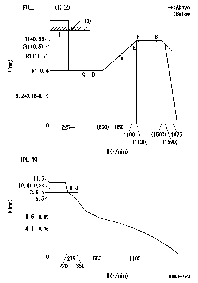
N:Pump speed
R:Rack position (mm)
(1)Torque cam stamping: T1
(2)Tolerance for racks not indicated: +-0.05mm.
(3)RACK LIMIT
----------
T1=H50
----------
----------
T1=H50
----------
Speed control lever angle

F:Full speed
I:Idle
(1)Accelerator lever
(2)Use the hole at R = aa
(3)Stopper bolt set position 'H'
----------
aa=35mm
----------
a=33deg+-5deg b=(42deg)+-3deg
----------
aa=35mm
----------
a=33deg+-5deg b=(42deg)+-3deg
Stop lever angle
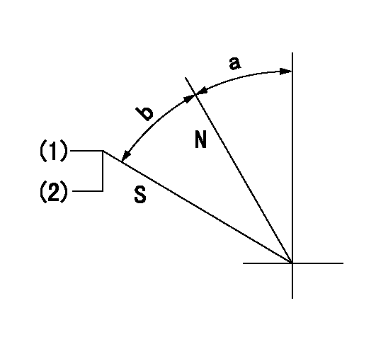
N:Pump normal
S:Stop the pump.
(1)Set the stopper bolt at pump speed = aa and rack position = bb (non-injection rack position). Confirm non-injection.
(2)After setting the stopper bolt, confirm non-injection at speed cc. Rack position = dd (non-injection rack position).
----------
aa=1450r/min bb=7.2-0.5mm cc=275r/min dd=(8.8)mm
----------
a=32.5deg+-5deg b=25deg+-5deg
----------
aa=1450r/min bb=7.2-0.5mm cc=275r/min dd=(8.8)mm
----------
a=32.5deg+-5deg b=25deg+-5deg
0000001501 MICRO SWITCH
Adjustment of the micro-switch
Adjust the bolt to obtain the following lever position when the micro-switch is ON.
(1)Speed N1
(2)Rack position Ra
----------
N1=400r/min Ra=9.2+-0.1mm
----------
----------
N1=400r/min Ra=9.2+-0.1mm
----------
Timing setting

(1)Pump vertical direction
(2)Position of timer's tooth at No 1 cylinder's beginning of injection
(3)B.T.D.C.: aa
(4)-
----------
aa=10deg
----------
a=(1deg)
----------
aa=10deg
----------
a=(1deg)
Information:
Cat ELC
Caterpillar provides Cat ELC (Extended Life Coolant) for use in the following applications:
Heavy-duty diesel engines
Automotive applicationsWhen Cat ELC is compared to conventional coolants, the Cat ELC anti-corrosion package is based on a different additive system. Cat ELC has been formulated with the correct amounts of additives. Superior corrosion protection is provided for all metals that are in engine cooling systems.Cat ELC extends the service life of the coolant to 12000 service hours or 6 years. Cat ELC does not require the frequent addition of the Cat ELC Extender additive. An Extender is the only additional maintenance that is needed at 6000 service hours or one half of the Cat ELC service life.Cat ELC is available in a 1:1 premixed cooling solution with distilled water. The premixed Cat ELC provides freeze protection to −37 °C (−34 °F). The premixed Cat ELC is recommended for the initial fill of the cooling system. The premixed Cat ELC is also recommended for topping off the cooling system.Cat ELC Concentrate is also available. Cat ELC Concentrate can be used to lower the freezing point to −52 °C (−62 °F) for arctic conditions.Containers of several sizes are available. Refer to this Special Publication, "Coolant Recommendations" article for available quantities and part numbers.Note: Cat ELC can be used in most diesel and gasoline OEM engines. Cat ELC meets
Have questions with 101607-6520?
Group cross 101607-6520 ZEXEL
Mitsubishi
101607-6520
9 400 615 709
ME077808
INJECTION-PUMP ASSEMBLY
6D16
6D16