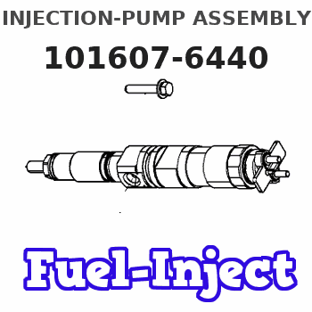
Information injection-pump assembly
BOSCH
9 400 615 701
9400615701
ZEXEL
101607-6440
1016076440
MITSUBISHI
ME077804
me077804
Rating:
Include in #2:
104139-1011
as _
Cross reference number
BOSCH
9 400 615 701
9400615701
ZEXEL
101607-6440
1016076440
MITSUBISHI
ME077804
me077804
Zexel num
Bosch num
Firm num
Name
101607-6440
9 400 615 701
ME077804 MITSUBISHI
INJECTION-PUMP ASSEMBLY
6D16 K
6D16 K
Calibration Data:
Adjustment conditions
Test oil
1404 Test oil ISO4113 or {SAEJ967d}
1404 Test oil ISO4113 or {SAEJ967d}
Test oil temperature
degC
40
40
45
Nozzle and nozzle holder
105780-8140
Bosch type code
EF8511/9A
Nozzle
105780-0000
Bosch type code
DN12SD12T
Nozzle holder
105780-2080
Bosch type code
EF8511/9
Opening pressure
MPa
17.2
Opening pressure
kgf/cm2
175
Injection pipe
Outer diameter - inner diameter - length (mm) mm 6-2-600
Outer diameter - inner diameter - length (mm) mm 6-2-600
Overflow valve
131424-8420
Overflow valve opening pressure
kPa
255
221
289
Overflow valve opening pressure
kgf/cm2
2.6
2.25
2.95
Tester oil delivery pressure
kPa
157
157
157
Tester oil delivery pressure
kgf/cm2
1.6
1.6
1.6
Direction of rotation (viewed from drive side)
Left L
Left L
Injection timing adjustment
Direction of rotation (viewed from drive side)
Left L
Left L
Injection order
1-5-3-6-
2-4
Pre-stroke
mm
3.2
3.15
3.25
Beginning of injection position
Governor side NO.1
Governor side NO.1
Difference between angles 1
Cal 1-5 deg. 60 59.5 60.5
Cal 1-5 deg. 60 59.5 60.5
Difference between angles 2
Cal 1-3 deg. 120 119.5 120.5
Cal 1-3 deg. 120 119.5 120.5
Difference between angles 3
Cal 1-6 deg. 180 179.5 180.5
Cal 1-6 deg. 180 179.5 180.5
Difference between angles 4
Cyl.1-2 deg. 240 239.5 240.5
Cyl.1-2 deg. 240 239.5 240.5
Difference between angles 5
Cal 1-4 deg. 300 299.5 300.5
Cal 1-4 deg. 300 299.5 300.5
Injection quantity adjustment
Adjusting point
-
Rack position
11.7
Pump speed
r/min
850
850
850
Each cylinder's injection qty
mm3/st.
77.4
75.1
79.7
Basic
*
Fixing the rack
*
Standard for adjustment of the maximum variation between cylinders
*
Injection quantity adjustment_02
Adjusting point
Z
Rack position
9.5+-0.5
Pump speed
r/min
800
800
800
Each cylinder's injection qty
mm3/st.
10.8
9.2
12.4
Fixing the rack
*
Standard for adjustment of the maximum variation between cylinders
*
Injection quantity adjustment_03
Adjusting point
A
Rack position
R1(11.7)
Pump speed
r/min
850
850
850
Average injection quantity
mm3/st.
77.4
76.4
78.4
Basic
*
Fixing the lever
*
Injection quantity adjustment_04
Adjusting point
B
Rack position
R1+0.55
Pump speed
r/min
1450
1450
1450
Average injection quantity
mm3/st.
87.7
83.7
91.7
Fixing the lever
*
Injection quantity adjustment_05
Adjusting point
C
Rack position
R1-0.4
Pump speed
r/min
500
500
500
Average injection quantity
mm3/st.
56
52
60
Fixing the lever
*
Injection quantity adjustment_06
Adjusting point
E
Rack position
(R1+0.5)
Pump speed
r/min
1100
1100
1100
Average injection quantity
mm3/st.
87.6
83.6
91.6
Fixing the lever
*
Injection quantity adjustment_07
Adjusting point
I
Rack position
-
Pump speed
r/min
100
100
100
Average injection quantity
mm3/st.
91
81
101
Fixing the lever
*
Rack limit
*
Timer adjustment
Pump speed
r/min
1150--
Advance angle
deg.
0
0
0
Remarks
Start
Start
Timer adjustment_02
Pump speed
r/min
1100
Advance angle
deg.
0.5
Timer adjustment_03
Pump speed
r/min
1450
Advance angle
deg.
6
5.5
6.5
Remarks
Finish
Finish
Test data Ex:
Governor adjustment
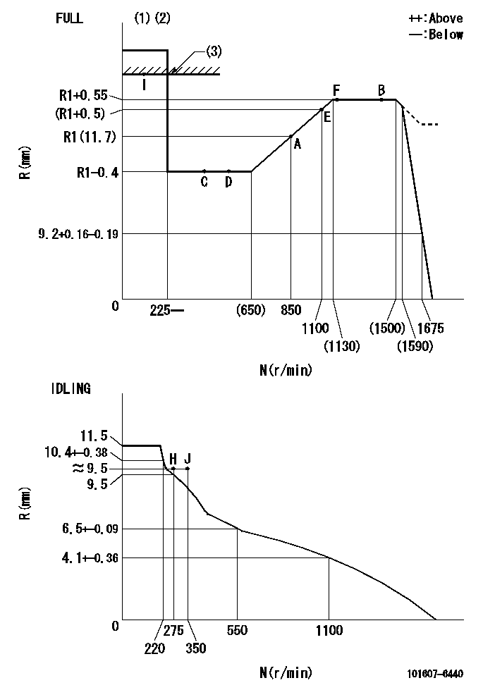
N:Pump speed
R:Rack position (mm)
(1)Torque cam stamping: T1
(2)Tolerance for racks not indicated: +-0.05mm.
(3)RACK LIMIT
----------
T1=H50
----------
----------
T1=H50
----------
Speed control lever angle

F:Full speed
I:Idle
(1)Stopper bolt set position 'H'
----------
----------
a=18.5deg+-5deg b=(42deg)+-3deg
----------
----------
a=18.5deg+-5deg b=(42deg)+-3deg
Stop lever angle

N:Engine manufacturer's normal use
S:Stop the pump.
(1)Set the stopper bolt at pump speed = aa and rack position = bb (non-injection rack position). Confirm non-injection.
(2)After setting the stopper bolt, confirm non-injection at speed cc. Rack position = dd (non-injection rack position).
(3)Rack position = approximately ee.
(4)Free (at delivery)
----------
aa=1450r/min bb=7.2-0.5mm cc=275r/min dd=(8.8)mm ee=15mm
----------
a=36.5deg+-5deg b=(25deg) c=13deg+-5deg
----------
aa=1450r/min bb=7.2-0.5mm cc=275r/min dd=(8.8)mm ee=15mm
----------
a=36.5deg+-5deg b=(25deg) c=13deg+-5deg
0000001501 LEVER

(A) Accelerator lever stopper bolt
(B) Link
(c) Nut
(D) Lever
(E) Pin
(f) lever
(G) Stopper bolt
(H) Return spring
(J) Pin (E) contacts lever.
(K) Load sensor terminal
(1)Black
(2)Blue-yellow
(3)Blue-red
Setting the accelerator lever angle, load sensor adjustment
1. Accelerator lever setting method
(1)Position the speed lever against the idle stopper bolt and fix.
(2)Screw in the accelerator lever stopper bolt (A) and back off the stopper bolt (A) from the position where the accelerator lever pin contacts the speed lever and set. (Gap: approx. 1 mm)
Tightening torque: 4.9~7 N.m {0.5~0.7 kgf.m}
2. Load sensor adjustment (See fig 1)
(1)Load sensor output measuring circuit
Apply DC5+-0.01V to the load sensor terminals and measure the output voltage.
(2)Load sensor output adjustment procedure
Hold the speed lever against the full side stopper bolt and fix. Adjust the load sensor output voltage to VF = 0.417+-0.1 V using the link (B) and then fix temporarily using nut (C).
Turn the speed lever from the idle side to the full side and confirm that output voltage VF = 0.417+-0.1 V is obtained. Confirm several times and then fix using nut (C).
Tightening torque: 3.4~4.9 N.m {0.35~0.5 kgf.m}
3. Setting the step motor's idle side stopper bolt
After adjustment in previous 1 and 2, position speed lever against idle stopper bolt and fix. Then, screw in stopper bolt G until step motor lever D's pin E contacts lever F. Back off 10+2 deg (approx. 3.5 mm) from this position and fix G. (See fig. 3)
4. Speed lever return confirmation
(1)Remove return spring (H) and confirm that the speed lever is returned to the idle position by the torsion spring.
(2)Reinstall the return spring (H) in its original position.
----------
----------
----------
----------
Timing setting

(1)Pump vertical direction
(2)Position of timer's tooth at No 1 cylinder's beginning of injection
(3)B.T.D.C.: aa
(4)-
----------
aa=10deg
----------
a=(2deg)
----------
aa=10deg
----------
a=(2deg)
Information:
Recommended engine warm-up procedure must be followed. Refer to the engine Operation and Maintenance Manual. Also refer to the relevant “Lubricant Viscosities for Ambient Temperatures” table footnote in this Special Publication.
Excessive engine idling time can contribute to excessive water in the crankcase oil, causing corrosion, sludge, and other problems. Excessive engine idling time can also lead to injector fouling, piston and combustion chamber deposits, corrosive damage, and increased oil consumption.
For proper selection of oil viscosity grade and oil type and/or specification, refer to this Special Publication, "Lubricant Specifications" section.Also, refer to this Special Publication, "Lubricant Viscosities" article.
Not following the recommendations found in the “Lubricant Viscosities for Ambient Temperatures” table and associated footnotes can lead to reduced performance and engine failure.
Do NOT use only the oil viscosities when determining the recommended oil for an engine compartment. The oil type (performance requirements) MUST also be used.
For easier cold weather starting, make sure that all of the components of the engine electrical system are properly maintained. All electrical wiring and connections should be free of the following: fraying, damaged insulation and corrosion. Batteries should be kept fully charged and warm. The batteries and the battery cables must be sized properly for the application.Various starting aids are available in order to assist with cold engine starts in low temperature conditions. Follow the recommendations that are provided by the manufacturer of the starting aid. Refer to the foreword section of this Special Publication, "Aftermarket Products and Warranty".For additional information concerning cold-weather operation, refer to this Special Publication, "Fuel Specifications" section. Also refer to this Special Publication, "Cooling System Specifications" section.Before attempting to start the engine, make sure that the oil in the engine is fluid enough to flow. Check the oil by removing the dipstick. If the oil will drip from the dipstick, then the oil should be fluid enough to allow the engine to start. Do not use oil that has been diluted with kerosene. Kerosene will evaporate in the engine. and cause the oil to thicken. Kerosene will cause swelling and softening of the silicone seals. Kerosene will dilute the oil additives. Dilution of the oil additives will reduce the performance, and reduce the engine protection that the additives provide.If the viscosity of the oil is changed for colder weather, also change the filter element. If the filter is not changed, the filter element and the filter housing can become a solid mass. After you change the oil, operate the engine in order to circulate the thinner oil.When you start a cold-soaked engine or when you operate an engine in ambient temperatures that are below −18°C (0°F), use base oils that can flow in low temperatures. These multigrade oils have lubricant viscosity grade of
Have questions with 101607-6440?
Group cross 101607-6440 ZEXEL
Mitsubishi
Mitsubishi
101607-6440
9 400 615 701
ME077804
INJECTION-PUMP ASSEMBLY
6D16
6D16