Information injection-pump assembly
BOSCH
9 400 615 690
9400615690
ZEXEL
101607-6292
1016076292
MITSUBISHI
ME076358
me076358

Rating:
Include in #2:
104746-6811
as _
Cross reference number
BOSCH
9 400 615 690
9400615690
ZEXEL
101607-6292
1016076292
MITSUBISHI
ME076358
me076358
Zexel num
Bosch num
Firm num
Name
101607-6292
9 400 615 690
ME076358 MITSUBISHI
INJECTION-PUMP ASSEMBLY
6D14 K
6D14 K
Calibration Data:
Adjustment conditions
Test oil
1404 Test oil ISO4113 or {SAEJ967d}
1404 Test oil ISO4113 or {SAEJ967d}
Test oil temperature
degC
40
40
45
Nozzle and nozzle holder
105780-8140
Bosch type code
EF8511/9A
Nozzle
105780-0000
Bosch type code
DN12SD12T
Nozzle holder
105780-2080
Bosch type code
EF8511/9
Opening pressure
MPa
17.2
Opening pressure
kgf/cm2
175
Injection pipe
Outer diameter - inner diameter - length (mm) mm 6-2-600
Outer diameter - inner diameter - length (mm) mm 6-2-600
Overflow valve
131424-5520
Overflow valve opening pressure
kPa
255
221
289
Overflow valve opening pressure
kgf/cm2
2.6
2.25
2.95
Tester oil delivery pressure
kPa
157
157
157
Tester oil delivery pressure
kgf/cm2
1.6
1.6
1.6
Direction of rotation (viewed from drive side)
Left L
Left L
Injection timing adjustment
Direction of rotation (viewed from drive side)
Left L
Left L
Injection order
1-5-3-6-
2-4
Pre-stroke
mm
3.3
3.25
3.35
Beginning of injection position
Governor side NO.1
Governor side NO.1
Difference between angles 1
Cal 1-5 deg. 60 59.5 60.5
Cal 1-5 deg. 60 59.5 60.5
Difference between angles 2
Cal 1-3 deg. 120 119.5 120.5
Cal 1-3 deg. 120 119.5 120.5
Difference between angles 3
Cal 1-6 deg. 180 179.5 180.5
Cal 1-6 deg. 180 179.5 180.5
Difference between angles 4
Cyl.1-2 deg. 240 239.5 240.5
Cyl.1-2 deg. 240 239.5 240.5
Difference between angles 5
Cal 1-4 deg. 300 299.5 300.5
Cal 1-4 deg. 300 299.5 300.5
Injection quantity adjustment
Adjusting point
-
Rack position
11.2
Pump speed
r/min
850
850
850
Each cylinder's injection qty
mm3/st.
57.7
56
59.4
Basic
*
Fixing the rack
*
Standard for adjustment of the maximum variation between cylinders
*
Injection quantity adjustment_02
Adjusting point
H
Rack position
9.5+-0.5
Pump speed
r/min
275
275
275
Each cylinder's injection qty
mm3/st.
13.7
11.6
15.8
Fixing the rack
*
Standard for adjustment of the maximum variation between cylinders
*
Injection quantity adjustment_03
Adjusting point
A
Rack position
R1(11.2)
Pump speed
r/min
850
850
850
Average injection quantity
mm3/st.
57.7
56.7
58.7
Basic
*
Fixing the lever
*
Injection quantity adjustment_04
Adjusting point
B
Rack position
R1+0.1
Pump speed
r/min
1450
1450
1450
Average injection quantity
mm3/st.
72.6
68.6
76.6
Fixing the lever
*
Injection quantity adjustment_05
Adjusting point
C
Rack position
R1+0.8
Pump speed
r/min
500
500
500
Average injection quantity
mm3/st.
59.7
55.7
63.7
Fixing the lever
*
Injection quantity adjustment_06
Adjusting point
D
Rack position
R1+1.25
Pump speed
r/min
300
300
300
Average injection quantity
mm3/st.
57.1
53.1
61.1
Fixing the lever
*
Injection quantity adjustment_07
Adjusting point
I
Rack position
-
Pump speed
r/min
100
100
100
Average injection quantity
mm3/st.
140
130
150
Fixing the lever
*
Rack limit
*
Timer adjustment
Pump speed
r/min
1250--
Advance angle
deg.
0
0
0
Remarks
Start
Start
Timer adjustment_02
Pump speed
r/min
1200
Advance angle
deg.
0.5
Timer adjustment_03
Pump speed
r/min
1400
Advance angle
deg.
5
4.5
5.5
Remarks
Finish
Finish
Test data Ex:
Governor adjustment
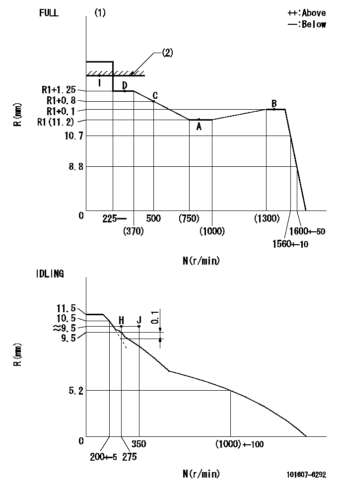
N:Pump speed
R:Rack position (mm)
(1)Torque cam stamping: T1
(2)RACK LIMIT
----------
T1=F21
----------
----------
T1=F21
----------
Speed control lever angle
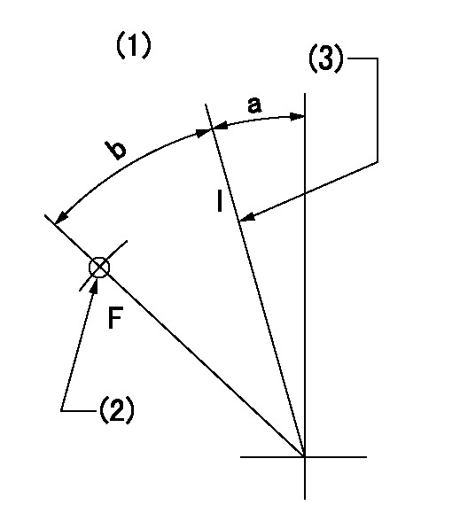
F:Full speed
I:Idle
(1)Accelerator lever
(2)Use the hole at R = aa
(3)Stopper bolt set position 'H'
----------
aa=29mm
----------
a=24deg+-5deg b=41deg+-3deg
----------
aa=29mm
----------
a=24deg+-5deg b=41deg+-3deg
Stop lever angle

N:Engine manufacturer's normal use
S:Stop the pump.
(1)Set the stopper bolt at pump speed = aa and rack position = bb (non-injection rack position). Confirm non-injection.
(2)After setting the stopper bolt, confirm non-injection at speed = cc. Rack position = actual (non-injection rack position).
(3)Rack position = approximately dd
(4)Free (at delivery)
(5)Use the hole above R = ee
----------
aa=1550r/min bb=7-0.5mm cc=275r/min dd=(16.8)mm ee=50mm
----------
a=36.5deg+-5deg b=(25deg) c=17deg+-5deg
----------
aa=1550r/min bb=7-0.5mm cc=275r/min dd=(16.8)mm ee=50mm
----------
a=36.5deg+-5deg b=(25deg) c=17deg+-5deg
0000001501 LEVER
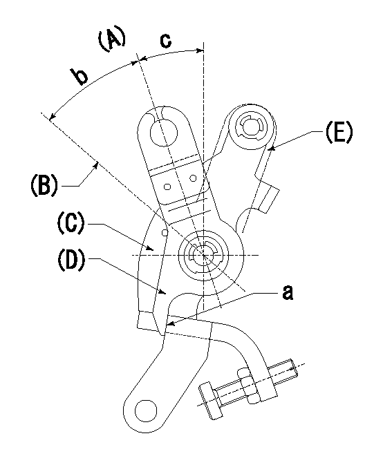
(A) Idle
(B) Full speed
(C) Base lever
(D) Accelerator lever
(E) Accelerator lever delivery position
1. Measure speed lever angle
(1)Measure the angle when the accelerator lever (D) contacted the base lever (C) at a.
----------
----------
b=41deg+-3deg c=24deg+-5deg
----------
----------
b=41deg+-3deg c=24deg+-5deg
0000001601 RACK SENSOR

V1:Supply voltage
V2f:Full side output voltage
V2i:Idle side output voltage
(A) Black
(B) Yellow
(C) Red
(D) Trimmer
(E): Shaft
(F) Nut
(G) Load lever
1. Load sensor adjustment
(1)Connect as shown in the above diagram and apply supply voltage V1.
(2)Hold the load lever (G) against the full side.
(3)Turn the shaft so that the voltage between (A) and (B) is V2.
(4)Hold the load lever (G) against the idle side.
(5)Adjust (D) so that the voltage between (A) and (B) is V2i.
(6)Repeat the above adjustments.
(7)Tighten the nut (F) at the point satisfying the standards.
(8)Hold the load lever against the full side stopper and the idle side stopper.
(9)At this time, confirm that the full side output voltage is V2f and the idle side output voltage is V2i.
----------
V1=3.57+-0.02V V2f=3+0.05V V2i=1+0.1V
----------
----------
V1=3.57+-0.02V V2f=3+0.05V V2i=1+0.1V
----------
0000001701 MICRO SWITCH
Adjustment of the micro-switch
Adjust the bolt to obtain the following lever position when the micro-switch is ON.
(1)Speed N1
(2)Rack position Ra
----------
N1=1600r/min Ra=8.8+-0.1mm
----------
----------
N1=1600r/min Ra=8.8+-0.1mm
----------
Timing setting

(1)Pump vertical direction
(2)Position of timer's tooth at No 1 cylinder's beginning of injection
(3)B.T.D.C.: aa
(4)-
----------
aa=13deg
----------
a=(3deg)
----------
aa=13deg
----------
a=(3deg)
Information:
Disconnect all electrical power from the monitor before removing components. Failure to disconnect the power could result in severe electrical shock or damage to the monitor. An electrical shock can cause severe personal injury or death.
Components that are inside of the monitor may be damaged by Electrostatic Discharge (ESD). Make sure that you wear a grounding strap whenever you handle the following components: circuit boards, memory modules and other internal components.
Wear a well grounded wrist strap and perform work in a static free environment. Electrostatic discharge can damage the monitor and components.
In order to remove the back cover or the top cover, perform the following procedure:
Disconnect the power from the monitor.
Illustration 1 g00858068
(1) 4 Screws (2) 8 Screws
Loosen the 8 screws (2) that secure the back cover in place. Remove the screws in order to access the power supply, the hard drive, and the floppy disk drive.
Loosen the 4 screws (1) that secure the top cover. Remove the screws in order to access the add-in cards and the memory modules.
In order to reinstall the back cover, position the back cover over the chassis and tighten the 8 screws (2). Align the two pins on the inside of the back cover that secure the hard drive bay.Note: Be careful not to push the vibration dampers (grommets) on the drive out of the sheet metal.
In order to reinstall the top cover, position the top cover over the chassis and tighten the 4 screws (1) .
Have questions with 101607-6292?
Group cross 101607-6292 ZEXEL
Mitsubishi
Mitsubishi
Mitsubishi
Mitsubishi
Mitsubishi
Mitsubishi
101607-6292
9 400 615 690
ME076358
INJECTION-PUMP ASSEMBLY
6D14
6D14