Information injection-pump assembly
ZEXEL
101607-6290
1016076290
Rating:
Cross reference number
ZEXEL
101607-6290
1016076290
Zexel num
Bosch num
Firm num
Name
101607-6290
INJECTION-PUMP ASSEMBLY
Calibration Data:
Adjustment conditions
Test oil
1404 Test oil ISO4113 or {SAEJ967d}
1404 Test oil ISO4113 or {SAEJ967d}
Test oil temperature
degC
40
40
45
Nozzle and nozzle holder
105780-8140
Bosch type code
EF8511/9A
Nozzle
105780-0000
Bosch type code
DN12SD12T
Nozzle holder
105780-2080
Bosch type code
EF8511/9
Opening pressure
MPa
17.2
Opening pressure
kgf/cm2
175
Injection pipe
Outer diameter - inner diameter - length (mm) mm 6-2-600
Outer diameter - inner diameter - length (mm) mm 6-2-600
Overflow valve
131424-5520
Overflow valve opening pressure
kPa
255
221
289
Overflow valve opening pressure
kgf/cm2
2.6
2.25
2.95
Tester oil delivery pressure
kPa
157
157
157
Tester oil delivery pressure
kgf/cm2
1.6
1.6
1.6
Direction of rotation (viewed from drive side)
Left L
Left L
Injection timing adjustment
Direction of rotation (viewed from drive side)
Left L
Left L
Injection order
1-5-3-6-
2-4
Pre-stroke
mm
3.3
3.25
3.35
Beginning of injection position
Governor side NO.1
Governor side NO.1
Difference between angles 1
Cal 1-5 deg. 60 59.5 60.5
Cal 1-5 deg. 60 59.5 60.5
Difference between angles 2
Cal 1-3 deg. 120 119.5 120.5
Cal 1-3 deg. 120 119.5 120.5
Difference between angles 3
Cal 1-6 deg. 180 179.5 180.5
Cal 1-6 deg. 180 179.5 180.5
Difference between angles 4
Cyl.1-2 deg. 240 239.5 240.5
Cyl.1-2 deg. 240 239.5 240.5
Difference between angles 5
Cal 1-4 deg. 300 299.5 300.5
Cal 1-4 deg. 300 299.5 300.5
Injection quantity adjustment
Adjusting point
-
Rack position
11.2
Pump speed
r/min
850
850
850
Each cylinder's injection qty
mm3/st.
57.7
56
59.4
Basic
*
Fixing the rack
*
Standard for adjustment of the maximum variation between cylinders
*
Injection quantity adjustment_02
Adjusting point
H
Rack position
9.5+-0.5
Pump speed
r/min
275
275
275
Each cylinder's injection qty
mm3/st.
13.7
11.6
15.8
Fixing the rack
*
Standard for adjustment of the maximum variation between cylinders
*
Injection quantity adjustment_03
Adjusting point
A
Rack position
R1(11.2)
Pump speed
r/min
850
850
850
Average injection quantity
mm3/st.
57.7
56.7
58.7
Basic
*
Fixing the lever
*
Injection quantity adjustment_04
Adjusting point
B
Rack position
R1+0.1
Pump speed
r/min
1450
1450
1450
Average injection quantity
mm3/st.
72.6
68.6
76.6
Fixing the lever
*
Injection quantity adjustment_05
Adjusting point
C
Rack position
R1+0.8
Pump speed
r/min
500
500
500
Average injection quantity
mm3/st.
59.7
55.7
63.7
Fixing the lever
*
Injection quantity adjustment_06
Adjusting point
D
Rack position
R1+1.25
Pump speed
r/min
300
300
300
Average injection quantity
mm3/st.
57.1
53.1
61.1
Fixing the lever
*
Injection quantity adjustment_07
Adjusting point
I
Rack position
-
Pump speed
r/min
100
100
100
Average injection quantity
mm3/st.
140
130
150
Fixing the lever
*
Rack limit
*
Timer adjustment
Pump speed
r/min
1250--
Advance angle
deg.
0
0
0
Remarks
Start
Start
Timer adjustment_02
Pump speed
r/min
1200
Advance angle
deg.
0.5
Timer adjustment_03
Pump speed
r/min
1400
Advance angle
deg.
5
4.5
5.5
Remarks
Finish
Finish
Test data Ex:
Governor adjustment
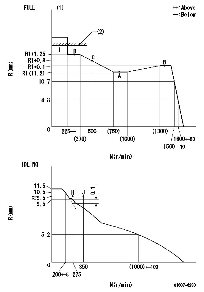
N:Pump speed
R:Rack position (mm)
(1)Torque cam stamping: T1
(2)RACK LIMIT
----------
T1=F21
----------
----------
T1=F21
----------
Speed control lever angle
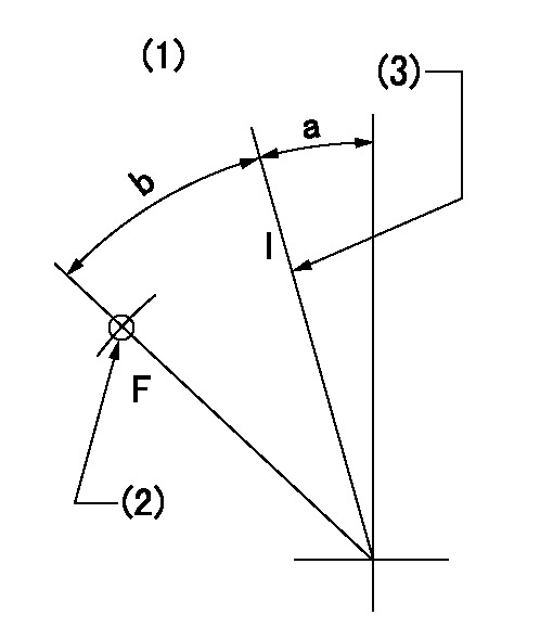
F:Full speed
I:Idle
(1)Accelerator lever
(2)Use the hole at R = aa
(3)Stopper bolt set position 'H'
----------
aa=29mm
----------
a=24deg+-5deg b=41deg+-3deg
----------
aa=29mm
----------
a=24deg+-5deg b=41deg+-3deg
Stop lever angle

N:Engine manufacturer's normal use
S:Stop the pump.
(1)Set the stopper bolt at pump speed = aa and rack position = bb (non-injection rack position). Confirm non-injection.
(2)After setting the stopper bolt, confirm non-injection at speed = cc. Rack position = actual (non-injection rack position).
(3)Rack position = approximately dd
(4)Free (at delivery)
(5)Use the hole above R = ee
----------
aa=1550r/min bb=7-0.5mm cc=275r/min dd=(16.8)mm ee=50mm
----------
a=36.5deg+-5deg b=(25deg) c=17deg+-5deg
----------
aa=1550r/min bb=7-0.5mm cc=275r/min dd=(16.8)mm ee=50mm
----------
a=36.5deg+-5deg b=(25deg) c=17deg+-5deg
0000001501 LEVER
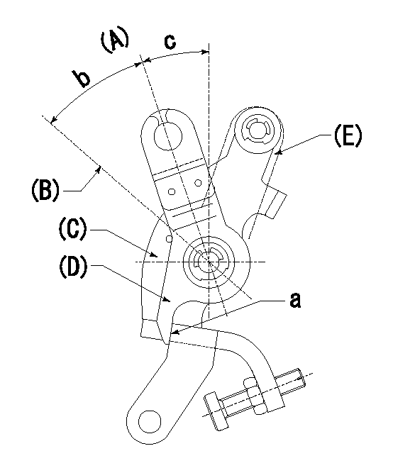
(A) Idle
(B) Full speed
(C) Base lever
(D) Accelerator lever
(E) Accelerator lever delivery position
1. Measure speed lever angle
(1)Measure the angle when the accelerator lever (D) contacted the base lever (C) at a.
----------
----------
b=41deg+-3deg c=24deg+-5deg
----------
----------
b=41deg+-3deg c=24deg+-5deg
0000001601 RACK SENSOR

V1:Supply voltage
V2f:Full side output voltage
V2i:Idle side output voltage
(A) Black
(B) Yellow
(C) Red
(D) Trimmer
(E): Shaft
(F) Nut
(G) Load lever
1. Load sensor adjustment
(1)Connect as shown in the above diagram and apply supply voltage V1.
(2)Hold the load lever (G) against the full side.
(3)Turn the shaft so that the voltage between (A) and (B) is V2.
(4)Hold the load lever (G) against the idle side.
(5)Adjust (D) so that the voltage between (A) and (B) is V2i.
(6)Repeat the above adjustments.
(7)Tighten the nut (F) at the point satisfying the standards.
(8)Hold the load lever against the full side stopper and the idle side stopper.
(9)At this time, confirm that the full side output voltage is V2f and the idle side output voltage is V2i.
----------
V1=3.57+-0.02V V2f=3+0.05V V2i=1+0.1V
----------
----------
V1=3.57+-0.02V V2f=3+0.05V V2i=1+0.1V
----------
0000001701 MICRO SWITCH
Adjust the bolt to obtain the following lever position when the micro-switch is OFF.
1. Microswitch adjustment (OPEN type)
Confirm with the lever angle at full.
(1)Speed N1
(2)Rack position Ra
----------
N1=1600r/min Ra=8.8+-0.1mm
----------
----------
N1=1600r/min Ra=8.8+-0.1mm
----------
Timing setting

(1)Pump vertical direction
(2)Position of timer's tooth at No 1 cylinder's beginning of injection
(3)B.T.D.C.: aa
(4)-
----------
aa=13deg
----------
a=(0deg)
----------
aa=13deg
----------
a=(0deg)
Information:
Operating Recommendations
The following guidelines are recommended when you use the monitor.
Avoid turning the system on and off frequently.
Never turn off the system when the indicator light for the hard drive is illuminated.
Always use the proper power down procedures as required by your operating system such as the "Shut Down" command in Microsoft Windows.
Do not turn off the monitor until a message appears. The message tells you that turning off the monitor is safe.
Do not operate the monitor when the covers are removed. An electrical shock hazard exists. In addition, removing the covers will disrupt the air flow. Removing the covers may result in overheating. All of the covers are required to maintain the EMI shield.Note: After you shut off the system, do not move the monitor or turn on the monitor. Wait until the hard drive has come to a complete stop (30 seconds). If you are using an external monitor, turn on the monitor first.Operator Access
Operator access is limited to the front panel of the monitor. The front panel includes the display and the touchscreen. Only authorized personnel and properly trained personnel are allowed access to other components.System Checkout
In order to power up the system, perform the following procedure:
Apply power to the monitor. The monitor performs a POST. During the test, the monitor checks the following devices: the processor board, the memory, the keyboard and certain peripheral devices.
The monitor displays the progress of the POST and the initialization of accessory devices.
If the system does not power up, or you notice other problems, refer to Troubleshooting, "Troubleshooting Checks".
The monitor will then display the start-up dialogs for the operating system that has been installed. If no software is installed, the following prompt is displayed:
Table 1
Insert bootable media in the appropriate drive. System Reset
In order to reset the monitor, press the following keys simultaneously: "Ctrl", "Alt" and "Delete". The keys are located on an attached keyboard. Follow the instructions for the operating system. During the reset, the monitor performs the following tasks:
Clears the RAM
Starts the POST
Initializes peripheral devices, such as drives and printers
Loads the operating system (if installed)After the reset, the monitor begins the POST.
Have questions with 101607-6290?
Group cross 101607-6290 ZEXEL
Mitsubishi
Mitsubishi
Mitsubishi
Mitsubishi
Mitsubishi
101607-6290
INJECTION-PUMP ASSEMBLY