Information injection-pump assembly
BOSCH
9 400 615 689
9400615689
ZEXEL
101607-6280
1016076280
MITSUBISHI
ME150462
me150462

Rating:
Service parts 101607-6280 INJECTION-PUMP ASSEMBLY:
1.
_
7.
COUPLING PLATE
8.
_
9.
_
11.
Nozzle and Holder
ME056371
12.
Open Pre:MPa(Kqf/cm2)
21.6{220}

15.
NOZZLE SET
Include in #1:
101607-6280
as INJECTION-PUMP ASSEMBLY
Include in #2:
104746-6801
as _
Cross reference number
BOSCH
9 400 615 689
9400615689
ZEXEL
101607-6280
1016076280
MITSUBISHI
ME150462
me150462
Zexel num
Bosch num
Firm num
Name
101607-6280
9 400 615 689
ME150462 MITSUBISHI
INJECTION-PUMP ASSEMBLY
6D22 * K 14BF INJECTION PUMP ASSY PE6AD PE
6D22 * K 14BF INJECTION PUMP ASSY PE6AD PE
Calibration Data:
Adjustment conditions
Test oil
1404 Test oil ISO4113 or {SAEJ967d}
1404 Test oil ISO4113 or {SAEJ967d}
Test oil temperature
degC
40
40
45
Nozzle and nozzle holder
105780-8140
Bosch type code
EF8511/9A
Nozzle
105780-0000
Bosch type code
DN12SD12T
Nozzle holder
105780-2080
Bosch type code
EF8511/9
Opening pressure
MPa
17.2
Opening pressure
kgf/cm2
175
Injection pipe
Outer diameter - inner diameter - length (mm) mm 6-2-600
Outer diameter - inner diameter - length (mm) mm 6-2-600
Overflow valve
131424-5120
Overflow valve opening pressure
kPa
255
221
289
Overflow valve opening pressure
kgf/cm2
2.6
2.25
2.95
Tester oil delivery pressure
kPa
157
157
157
Tester oil delivery pressure
kgf/cm2
1.6
1.6
1.6
Direction of rotation (viewed from drive side)
Right R
Right R
Injection timing adjustment
Direction of rotation (viewed from drive side)
Right R
Right R
Injection order
1-5-3-6-
2-4
Pre-stroke
mm
4.5
4.45
4.55
Beginning of injection position
Governor side NO.1
Governor side NO.1
Difference between angles 1
Cal 1-5 deg. 60 59.5 60.5
Cal 1-5 deg. 60 59.5 60.5
Difference between angles 2
Cal 1-3 deg. 120 119.5 120.5
Cal 1-3 deg. 120 119.5 120.5
Difference between angles 3
Cal 1-6 deg. 180 179.5 180.5
Cal 1-6 deg. 180 179.5 180.5
Difference between angles 4
Cyl.1-2 deg. 240 239.5 240.5
Cyl.1-2 deg. 240 239.5 240.5
Difference between angles 5
Cal 1-4 deg. 300 299.5 300.5
Cal 1-4 deg. 300 299.5 300.5
Injection quantity adjustment
Adjusting point
-
Rack position
9.9
Pump speed
r/min
700
700
700
Each cylinder's injection qty
mm3/st.
120
116.6
123.4
Basic
*
Fixing the rack
*
Standard for adjustment of the maximum variation between cylinders
*
Injection quantity adjustment_02
Adjusting point
C
Rack position
8+-0.5
Pump speed
r/min
225
225
225
Each cylinder's injection qty
mm3/st.
18.5
15.7
21.3
Fixing the rack
*
Standard for adjustment of the maximum variation between cylinders
*
Injection quantity adjustment_03
Adjusting point
A
Rack position
R1(9.9)
Pump speed
r/min
700
700
700
Average injection quantity
mm3/st.
120
119
121
Basic
*
Fixing the lever
*
Injection quantity adjustment_04
Adjusting point
B
Rack position
R1(9.9)
Pump speed
r/min
1100
1100
1100
Average injection quantity
mm3/st.
123.7
121.2
126.2
Difference in delivery
mm3/st.
9
9
9
Fixing the lever
*
Injection quantity adjustment_05
Adjusting point
E
Rack position
-
Pump speed
r/min
100
100
100
Average injection quantity
mm3/st.
140
100
180
Fixing the lever
*
Remarks
After startup boost setting
After startup boost setting
Timer adjustment
Pump speed
r/min
800
Advance angle
deg.
0.5
Timer adjustment_02
Pump speed
r/min
1000
Advance angle
deg.
0.9
0.4
1.4
Timer adjustment_03
Pump speed
r/min
1150
Advance angle
deg.
3
2.5
3.5
Timer adjustment_04
Pump speed
r/min
-
Advance angle
deg.
4
4
5
Remarks
Measure the actual speed, stop
Measure the actual speed, stop
Test data Ex:
Governor adjustment
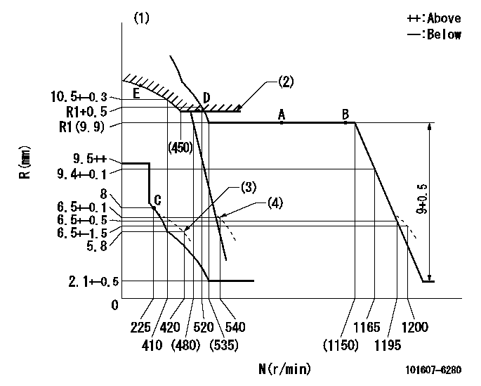
N:Pump speed
R:Rack position (mm)
(1)Tolerance for racks not indicated: +-0.05mm.
(2)Excess fuel setting for starting: SXL
(3)Damper spring setting
(4)When air cylinder is operating.
----------
SXL=R1+0.2mm
----------
----------
SXL=R1+0.2mm
----------
Speed control lever angle
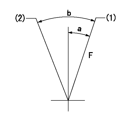
F:Full speed
(1)Set the pump speed at aa
(2)Set the pump speed at bb.
----------
aa=1165r/min bb=540r/min
----------
a=10deg+-5deg b=(15deg)+-5deg
----------
aa=1165r/min bb=540r/min
----------
a=10deg+-5deg b=(15deg)+-5deg
0000000901
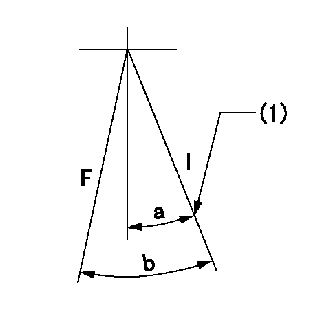
F:Full load
I:Idle
(1)Stopper bolt setting
----------
----------
a=21deg+-5deg b=28.5deg+-3deg
----------
----------
a=21deg+-5deg b=28.5deg+-3deg
Stop lever angle
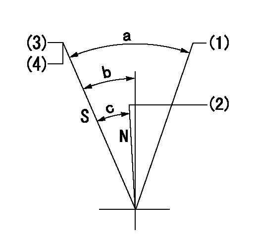
N:Pump normal
S:Stop the pump.
(1)Free (at delivery)
(2)Rack position = aa
(3)Rack position bb
(4)Stopper bolt setting
----------
aa=13.5mm bb=6-0.5mm
----------
a=(52deg) b=30deg+7deg-5deg c=24deg+-5deg
----------
aa=13.5mm bb=6-0.5mm
----------
a=(52deg) b=30deg+7deg-5deg c=24deg+-5deg
0000001501 MICRO SWITCH
Adjustment of the micro-switch
Adjust the bolt to obtain the following lever position when the micro-switch is ON.
(1)Speed N1
(2)Rack position Ra
----------
N1=325r/min Ra=7.3+-0.1mm
----------
----------
N1=325r/min Ra=7.3+-0.1mm
----------
0000001601 ACS
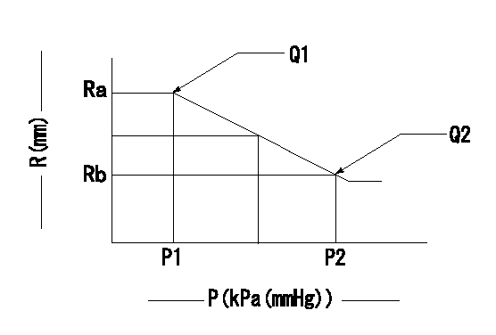
Aneroid compensator adjustment
(1)Adjust the clearance between the aneroid compensator's main body and the push rod to L1.
(2)Pump speed N1 at load lever's full position.
(3)Screw in the aneroid compensator body to obtain the performance shown in the graph above.
----------
L1=0.1~0.5mm N1=700r/min
----------
Ra=9.9mm Rb=(9.2)mm P1=(88.6)kPa((665)mmHg) P2=69+-0.7kPa(518+-5mmHg) Q1=120+-1cm3/1000st Q2=100.5+-1cm3/1000st
----------
L1=0.1~0.5mm N1=700r/min
----------
Ra=9.9mm Rb=(9.2)mm P1=(88.6)kPa((665)mmHg) P2=69+-0.7kPa(518+-5mmHg) Q1=120+-1cm3/1000st Q2=100.5+-1cm3/1000st
Timing setting

(1)Pump vertical direction
(2)Coupling's key groove position at No 1 cylinder's beginning of injection
(3)-
(4)-
----------
----------
a=(7deg)
----------
----------
a=(7deg)
Information:
- Generator Monitoring SystemI/O - Input/OutputMMS - Marine Monitoring SystemMMS II - Marine Monitoring System IIPLC - Programmable Logic ControllerThe 203-7811 Engine Monitoring Control Group is the service replacement for the 146-3117 Monitoring Control and the 162-1662 Monitoring Control that are used in MMS. The 203-7811 Engine Monitoring Control Group uses Wonderware as the "Graphic Display Application".The 203-7810 Engine Monitoring Control Group is the optional monitor that is used in the MMS II and the GMS. The 203-7810 Engine Monitoring Control Group uses the RSView as the "Graphic Display Application".When these engine monitoring control groups are used as service replacements in the field, use the procedure that follows to register the software to the user. This procedure can be done when the engine monitoring control group is connected to the PLC. This procedure can also be done when the engine monitoring control group is not connected to the PLC.
Connect a keyboard that is compatible with the PS/2 style of connector. Connect electrical power to the monitor.
Turn on the power.
When you are prompted, accept the license agreement. Press the "Next" button.
Enter the Microsoft Windows NT product identification number. This number is located on the right side of the computer. Press "Next".
When the message indicates that the system could not complete the login, select "OK".
Input "Administrator" for the login username. Input "3600" for the login password.
After a successful login as "Administrator", do one of the items that follow:
Restart the computer.
Close all of the programs and use a different login username.
When the message indicates that the system could not complete the login, select "OK".
Input "Operator" for the login username. Input "password" for the login password.
After a successful login as "Operator", one of the items that follow will occur:
If a 203-7811 Engine Monitoring Control Group is used, the Wonderware I/O Server and the Window Viewer will be started.
If a 203-7810 Engine Monitoring Control Group is used, the RSView Runtime will be started.
Remove the keyboard. The setup is complete.In applications that use Wonderware or RSView, the engine monitoring control group must be connected to the PLC in order for the data to be displayed.After a successful login to the "Operator" account, the computer will automatically start and the computer will start the application in the "Operator" account. The automatic start-up can be bypassed by doing the operations that follow:
Attach a keyboard.
Hold the "shift" key in the down position while the start-up of the computer is initiated.
Have questions with 101607-6280?
Group cross 101607-6280 ZEXEL
Mitsubishi
Mitsubishi
Mitsubishi
Mitsubishi
Mitsubishi
101607-6280
9 400 615 689
ME150462
INJECTION-PUMP ASSEMBLY
6D22
6D22