Information injection-pump assembly
BOSCH
9 400 615 686
9400615686
ZEXEL
101607-6250
1016076250
MITSUBISHI
ME047790
me047790

Rating:
Include in #2:
104746-6771
as _
Cross reference number
BOSCH
9 400 615 686
9400615686
ZEXEL
101607-6250
1016076250
MITSUBISHI
ME047790
me047790
Zexel num
Bosch num
Firm num
Name
101607-6250
9 400 615 686
ME047790 MITSUBISHI
INJECTION-PUMP ASSEMBLY
6D14T K
6D14T K
Calibration Data:
Adjustment conditions
Test oil
1404 Test oil ISO4113 or {SAEJ967d}
1404 Test oil ISO4113 or {SAEJ967d}
Test oil temperature
degC
40
40
45
Nozzle and nozzle holder
105780-8140
Bosch type code
EF8511/9A
Nozzle
105780-0000
Bosch type code
DN12SD12T
Nozzle holder
105780-2080
Bosch type code
EF8511/9
Opening pressure
MPa
17.2
Opening pressure
kgf/cm2
175
Injection pipe
Outer diameter - inner diameter - length (mm) mm 6-2-600
Outer diameter - inner diameter - length (mm) mm 6-2-600
Overflow valve
131424-5520
Overflow valve opening pressure
kPa
255
221
289
Overflow valve opening pressure
kgf/cm2
2.6
2.25
2.95
Tester oil delivery pressure
kPa
157
157
157
Tester oil delivery pressure
kgf/cm2
1.6
1.6
1.6
Direction of rotation (viewed from drive side)
Left L
Left L
Injection timing adjustment
Direction of rotation (viewed from drive side)
Left L
Left L
Injection order
1-5-3-6-
2-4
Pre-stroke
mm
3
2.95
3.05
Beginning of injection position
Governor side NO.1
Governor side NO.1
Difference between angles 1
Cal 1-5 deg. 60 59.5 60.5
Cal 1-5 deg. 60 59.5 60.5
Difference between angles 2
Cal 1-3 deg. 120 119.5 120.5
Cal 1-3 deg. 120 119.5 120.5
Difference between angles 3
Cal 1-6 deg. 180 179.5 180.5
Cal 1-6 deg. 180 179.5 180.5
Difference between angles 4
Cyl.1-2 deg. 240 239.5 240.5
Cyl.1-2 deg. 240 239.5 240.5
Difference between angles 5
Cal 1-4 deg. 300 299.5 300.5
Cal 1-4 deg. 300 299.5 300.5
Injection quantity adjustment
Adjusting point
A
Rack position
10
Pump speed
r/min
1400
1400
1400
Average injection quantity
mm3/st.
88.9
87.9
89.9
Max. variation between cylinders
%
0
-2.5
2.5
Basic
*
Fixing the lever
*
Injection quantity adjustment_02
Adjusting point
C
Rack position
7.8+-0.5
Pump speed
r/min
340
340
340
Average injection quantity
mm3/st.
9.2
7.7
10.7
Max. variation between cylinders
%
0
-15
15
Fixing the rack
*
Timer adjustment
Pump speed
r/min
1050--
Advance angle
deg.
0
0
0
Remarks
Start
Start
Timer adjustment_02
Pump speed
r/min
1000
Advance angle
deg.
0.5
Timer adjustment_03
Pump speed
r/min
1400
Advance angle
deg.
2
1.5
2.5
Remarks
Finish
Finish
Test data Ex:
Governor adjustment
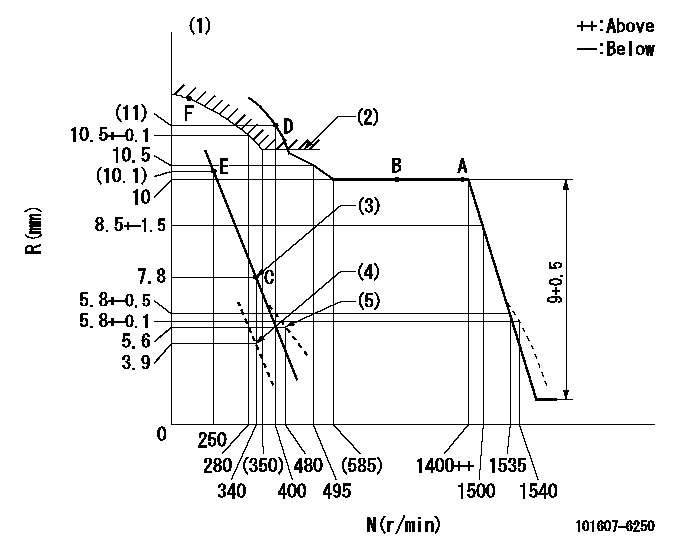
N:Pump speed
R:Rack position (mm)
(1)Tolerance for racks not indicated: +-0.05mm.
(2)Excess fuel setting for starting: SXL (N = N1)
(3)Main spring setting
(4)Set idle sub-spring
(5)Damper spring setting
----------
SXL=10+0.2mm N1=500r/min
----------
----------
SXL=10+0.2mm N1=500r/min
----------
Speed control lever angle

F:Full speed
I:Idle
(1)Stopper bolt setting
----------
----------
a=18deg+-5deg b=3deg+-5deg
----------
----------
a=18deg+-5deg b=3deg+-5deg
0000000901

F:Full load
(1)Fix the lever at the full load position
----------
----------
a=16deg+-5deg
----------
----------
a=16deg+-5deg
Stop lever angle
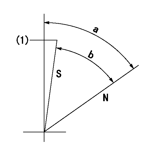
N:Pump normal
S:Stop the pump.
(1)Set stopper bolt so that rack position = aa (after adjusting, apply red paint).
----------
aa=4.5-0.5mm
----------
a=57deg+-5deg b=57deg+7deg-5deg
----------
aa=4.5-0.5mm
----------
a=57deg+-5deg b=57deg+7deg-5deg
Timing setting

(1)Pump vertical direction
(2)Position of timer's tooth at No 1 cylinder's beginning of injection
(3)B.T.D.C.: aa
(4)-
----------
aa=14deg
----------
a=(1deg)
----------
aa=14deg
----------
a=(1deg)
Information:
Accessing the BIOS Setup Screen
The BIOS Setup screen can be entered during powerup by pressing the "F2" key immediately following the RAM test. Because the keyboard is not buffered during this stage of powerup, the "F2 " key may need to be repeatedly depressed to enter the BIOS Setup screen.Note: You may need to determine the installed version of the BIOS before contacting technical support. The BIOS Setup screen displays the installed version of the BIOS.BIOS Setup Program
The BIOS Setup is a menu driven program that allows the user to select from a variety of configurations. The setup program contains descriptive information for each configuration setting that is available.Because the BIOS field is able to be upgraded, the exact BIOS settings may change with BIOS revisions. The following information may not include all the options in future BIOS revisions.The five main tables that follow are included in the BIOS Setup program:
MAIN
ADVANCED
HARDWARE
BOOT
EXITFactory Default Settings
MAIN Tab
Table 1
System Time (enter time here)
System Date (enter date here)
Legacy Diskette A: 1.44/1.25 MB 3.5"
Primary Master Std. EIDE 30 Gig
Primary Slave (none)
Cache RAM 512 K
System Memory 640 KB
Extended Memory 64 Meg ADVANCED Tab
Table 2
Backlight Timeout 15 minutes (1)
PCI Configuration (2) PCI/PNP ISA DMA Resource Exclusion - all available
PCI/PNP IRQ Resource Exclusion - all available
PCI/PNP ISA UMB Region Exclusion - if KTCX15 then D000-D3FF Reserved, Not Shadowed. Otherwise, all available
I/O Device Configuration Serial Port A - Auto
Serial Port B - Auto
Mode - Normal
Parallel Port - Auto
Mode - Bi-directional
Floppy Disk Controller - Enabled (3)
PS/2 Mouse Auto Detect
Reset Configuration Data No
Large Disk Access Mode DOS
Secured Setup Configurations No
Memory Parity Check ECC
DMI Event Logging View DMI event log - Enter
Event logging - Enabled
Mark DMI events as read - Enter
Clear all DMI event logs - No
Installed O/S Other
( 1 ) The timer can be set to disable the backlight after 30 seconds, 1 minute, 2 minutes, 4 minutes, 6 minutes, 8 minutes, 12 minutes, and 15 minutes.
( 2 ) Allows the user to reserve specific resources for the ISA card.
( 3 ) Use this setting in order to disable the floppy diskette drive.HARDWARE Tab
Table 3
Enable Voltage Reading Yes
3.3 Volts: 3.17 to 3.43
5 Volts: 4.75 to 5.25
12 Volts: 11.4 to 12.6
-5 Volts: -4.25 to -5.75
-12 Volts: -10.8 to -12.35
Enable Fan Speed Yes
System Fan 2520 RPM minimum
Enable Temperature Yes
Temperature
60 °C (140 °F) maximum BOOT Tab
Table 4
1 diskette drive
2 removable devices
3 hard drive
4 ATAPI CDROM drive
Hard Drive 1. (current hard drive)
2. bootable add-in card
Removable Format
EXIT Tab
Table 5
Exit saving changes
Exit discarding changes
Load setup defaults (1)
Have questions with 101607-6250?
Group cross 101607-6250 ZEXEL
Mitsubishi
Mitsubishi
Mitsubishi
Mitsubishi
Mitsubishi
101607-6250
9 400 615 686
ME047790
INJECTION-PUMP ASSEMBLY
6D14T
6D14T