Information injection-pump assembly
BOSCH
9 400 615 683
9400615683
ZEXEL
101607-6221
1016076221
MITSUBISHI
ME076382
me076382

Rating:
Service parts 101607-6221 INJECTION-PUMP ASSEMBLY:
1.
_
6.
COUPLING PLATE
7.
COUPLING PLATE
8.
_
9.
_
11.
Nozzle and Holder
12.
Open Pre:MPa(Kqf/cm2)
15.7(160)/21.6(220)
14.
NOZZLE
Include in #1:
101607-6221
as INJECTION-PUMP ASSEMBLY
Include in #2:
104746-6890
as _
Cross reference number
BOSCH
9 400 615 683
9400615683
ZEXEL
101607-6221
1016076221
MITSUBISHI
ME076382
me076382
Zexel num
Bosch num
Firm num
Name
101607-6221
9 400 615 683
ME076382 MITSUBISHI
INJECTION-PUMP ASSEMBLY
6D16 K
6D16 K
Calibration Data:
Adjustment conditions
Test oil
1404 Test oil ISO4113 or {SAEJ967d}
1404 Test oil ISO4113 or {SAEJ967d}
Test oil temperature
degC
40
40
45
Nozzle and nozzle holder
105780-8140
Bosch type code
EF8511/9A
Nozzle
105780-0000
Bosch type code
DN12SD12T
Nozzle holder
105780-2080
Bosch type code
EF8511/9
Opening pressure
MPa
17.2
Opening pressure
kgf/cm2
175
Injection pipe
Outer diameter - inner diameter - length (mm) mm 6-2-600
Outer diameter - inner diameter - length (mm) mm 6-2-600
Overflow valve
131424-8420
Overflow valve opening pressure
kPa
255
221
289
Overflow valve opening pressure
kgf/cm2
2.6
2.25
2.95
Tester oil delivery pressure
kPa
157
157
157
Tester oil delivery pressure
kgf/cm2
1.6
1.6
1.6
Direction of rotation (viewed from drive side)
Left L
Left L
Injection timing adjustment
Direction of rotation (viewed from drive side)
Left L
Left L
Injection order
1-5-3-6-
2-4
Pre-stroke
mm
3.2
3.15
3.25
Beginning of injection position
Governor side NO.1
Governor side NO.1
Difference between angles 1
Cal 1-5 deg. 60 59.5 60.5
Cal 1-5 deg. 60 59.5 60.5
Difference between angles 2
Cal 1-3 deg. 120 119.5 120.5
Cal 1-3 deg. 120 119.5 120.5
Difference between angles 3
Cal 1-6 deg. 180 179.5 180.5
Cal 1-6 deg. 180 179.5 180.5
Difference between angles 4
Cyl.1-2 deg. 240 239.5 240.5
Cyl.1-2 deg. 240 239.5 240.5
Difference between angles 5
Cal 1-4 deg. 300 299.5 300.5
Cal 1-4 deg. 300 299.5 300.5
Injection quantity adjustment
Adjusting point
-
Rack position
11.7
Pump speed
r/min
850
850
850
Each cylinder's injection qty
mm3/st.
77.4
75.1
79.7
Basic
*
Fixing the rack
*
Standard for adjustment of the maximum variation between cylinders
*
Injection quantity adjustment_02
Adjusting point
Z
Rack position
9.5+-0.5
Pump speed
r/min
800
800
800
Each cylinder's injection qty
mm3/st.
10.8
9.2
12.4
Fixing the rack
*
Standard for adjustment of the maximum variation between cylinders
*
Injection quantity adjustment_03
Adjusting point
A
Rack position
R1(11.7)
Pump speed
r/min
850
850
850
Average injection quantity
mm3/st.
77.4
76.4
78.4
Basic
*
Fixing the lever
*
Injection quantity adjustment_04
Adjusting point
B
Rack position
R1+0.55
Pump speed
r/min
1450
1450
1450
Average injection quantity
mm3/st.
87.7
83.7
91.7
Fixing the lever
*
Injection quantity adjustment_05
Adjusting point
C
Rack position
R1-0.4
Pump speed
r/min
500
500
500
Average injection quantity
mm3/st.
56
52
60
Fixing the lever
*
Injection quantity adjustment_06
Adjusting point
E
Rack position
(R1+0.5)
Pump speed
r/min
1100
1100
1100
Average injection quantity
mm3/st.
87.6
83.6
91.6
Fixing the lever
*
Injection quantity adjustment_07
Adjusting point
I
Rack position
-
Pump speed
r/min
100
100
100
Average injection quantity
mm3/st.
91
81
101
Fixing the lever
*
Rack limit
*
Timer adjustment
Pump speed
r/min
1080
Advance angle
deg.
0.5
Timer adjustment_02
Pump speed
r/min
-
Advance angle
deg.
2.5
2.5
2.5
Remarks
Measure the actual speed.
Measure the actual speed.
Timer adjustment_03
Pump speed
r/min
1390
Advance angle
deg.
6
5.5
6.5
Remarks
Finish
Finish
Test data Ex:
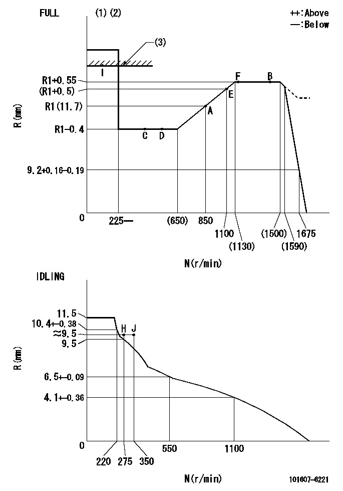
Governor adjustment

N:Pump speed
R:Rack position (mm)
(1)Torque cam stamping: T1
(2)Tolerance for racks not indicated: +-0.05mm.
(3)RACK LIMIT
----------
T1=H50
----------
----------
T1=H50
----------
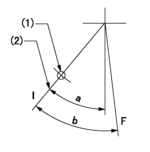
Speed control lever angle

F:Full speed
I:Idle
(1)Use the hole at R = aa
(2)Stopper bolt set position 'H'
----------
aa=35mm
----------
a=41deg+-5deg b=(42deg)+-3deg
----------
aa=35mm
----------
a=41deg+-5deg b=(42deg)+-3deg
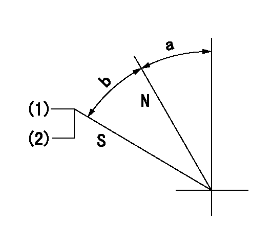
Stop lever angle

N:Pump normal
S:Stop the pump.
(1)Set the stopper bolt at pump speed = aa and rack position = bb (non-injection rack position). Confirm non-injection.
(2)After setting the stopper bolt, confirm non-injection at speed cc. Rack position = dd (non-injection rack position).
----------
aa=1450r/min bb=7.2-0.5mm cc=275r/min dd=(8.8)mm
----------
a=32.5deg+-5deg b=25deg+-5deg
----------
aa=1450r/min bb=7.2-0.5mm cc=275r/min dd=(8.8)mm
----------
a=32.5deg+-5deg b=25deg+-5deg
0000001501 MICRO SWITCH
Adjustment of the micro-switch
Adjust the bolt to obtain the following lever position when the micro-switch is ON.
(1)Speed N1
(2)Rack position Ra
----------
N1=400r/min Ra=9.2+-0.1mm
----------
----------
N1=400r/min Ra=9.2+-0.1mm
----------
Timing setting

(1)Pump vertical direction
(2)Position of timer's tooth at No 1 cylinder's beginning of injection
(3)B.T.D.C.: aa
(4)-
----------
aa=10deg
----------
a=(3deg)
----------
aa=10deg
----------
a=(3deg)
Information:
Troubleshooting the -5 Cylinder Injector : Current Below Normal Code
Illustration 1 g01336507
Schematic for the 16-cylinder injectors
Illustration 2 g01336555
Schematic for the 20-cylinder injectors
Electrical Shock Hazard. The unit injector system uses 90 - 120 volts. The ECM sends this signal to the unit injectors. Do not come in contact with the unit injector harness connector while the engine is operating. Failure to follow this instruction could resulting in personal injury or death.
Table 3
Troubleshooting Test Steps Value Result
A. Check for an Intermittent High Resistance Short Circuit to Ground.
1. Disconnect the rail harness from the ECM. Inspect the connectors and terminals for moisture, corrosion, and other damage. Inspect the condition of the wires. Perform a
45 N (10 lb) pull test on the wires.
Connectors and wiring Result: A problem with the connectors or wiring is found..
Repair the parts, as needed.
Stop
Result: The connectors and wiring appear to be OK.
Proceed to the next test step.
2. On the rail harness, locate any one of the three terminals for the two injectors that have the -5 code.
3. Measure the resistance from the terminal on the rail harness to chassis ground. Ensure that the ground connection is good.
Have questions with 101607-6221?
Group cross 101607-6221 ZEXEL
Mitsubishi
Mitsubishi
Mitsubishi
101607-6221
9 400 615 683
ME076382
INJECTION-PUMP ASSEMBLY
6D16
6D16