Information injection-pump assembly
BOSCH
9 400 615 681
9400615681
ZEXEL
101607-6200
1016076200
MITSUBISHI
ME076999
me076999

Rating:
Include in #2:
104746-6861
as _
Cross reference number
BOSCH
9 400 615 681
9400615681
ZEXEL
101607-6200
1016076200
MITSUBISHI
ME076999
me076999
Zexel num
Bosch num
Firm num
Name
Calibration Data:
Adjustment conditions
Test oil
1404 Test oil ISO4113 or {SAEJ967d}
1404 Test oil ISO4113 or {SAEJ967d}
Test oil temperature
degC
40
40
45
Nozzle and nozzle holder
105780-8140
Bosch type code
EF8511/9A
Nozzle
105780-0000
Bosch type code
DN12SD12T
Nozzle holder
105780-2080
Bosch type code
EF8511/9
Opening pressure
MPa
17.2
Opening pressure
kgf/cm2
175
Injection pipe
Outer diameter - inner diameter - length (mm) mm 6-2-600
Outer diameter - inner diameter - length (mm) mm 6-2-600
Overflow valve
131424-8420
Overflow valve opening pressure
kPa
255
221
289
Overflow valve opening pressure
kgf/cm2
2.6
2.25
2.95
Tester oil delivery pressure
kPa
157
157
157
Tester oil delivery pressure
kgf/cm2
1.6
1.6
1.6
Direction of rotation (viewed from drive side)
Left L
Left L
Injection timing adjustment
Direction of rotation (viewed from drive side)
Left L
Left L
Injection order
1-5-3-6-
2-4
Pre-stroke
mm
3.2
3.15
3.25
Beginning of injection position
Governor side NO.1
Governor side NO.1
Difference between angles 1
Cal 1-5 deg. 60 59.5 60.5
Cal 1-5 deg. 60 59.5 60.5
Difference between angles 2
Cal 1-3 deg. 120 119.5 120.5
Cal 1-3 deg. 120 119.5 120.5
Difference between angles 3
Cal 1-6 deg. 180 179.5 180.5
Cal 1-6 deg. 180 179.5 180.5
Difference between angles 4
Cyl.1-2 deg. 240 239.5 240.5
Cyl.1-2 deg. 240 239.5 240.5
Difference between angles 5
Cal 1-4 deg. 300 299.5 300.5
Cal 1-4 deg. 300 299.5 300.5
Injection quantity adjustment
Adjusting point
-
Rack position
12
Pump speed
r/min
850
850
850
Each cylinder's injection qty
mm3/st.
85.1
82.5
87.7
Basic
*
Fixing the rack
*
Standard for adjustment of the maximum variation between cylinders
*
Injection quantity adjustment_02
Adjusting point
Z
Rack position
9.5+-0.5
Pump speed
r/min
800
800
800
Each cylinder's injection qty
mm3/st.
10.8
9.2
12.4
Fixing the rack
*
Standard for adjustment of the maximum variation between cylinders
*
Injection quantity adjustment_03
Adjusting point
A
Rack position
R1(12)
Pump speed
r/min
850
850
850
Average injection quantity
mm3/st.
85.1
84.1
86.1
Basic
*
Fixing the lever
*
Injection quantity adjustment_04
Adjusting point
B
Rack position
R1+0.85
Pump speed
r/min
1450
1450
1450
Average injection quantity
mm3/st.
99.9
95.9
103.9
Fixing the lever
*
Injection quantity adjustment_05
Adjusting point
I
Rack position
-
Pump speed
r/min
100
100
100
Average injection quantity
mm3/st.
91
81
101
Fixing the lever
*
Rack limit
*
Timer adjustment
Pump speed
r/min
1100
Advance angle
deg.
0.5
Timer adjustment_02
Pump speed
r/min
1300
Advance angle
deg.
2.5
2.5
3.5
Timer adjustment_03
Pump speed
r/min
1450
Advance angle
deg.
6
5.5
6.5
Remarks
Finish
Finish
Test data Ex:
Governor adjustment
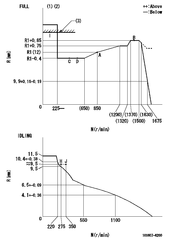
N:Pump speed
R:Rack position (mm)
(1)Torque cam stamping: T1
(2)Tolerance for racks not indicated: +-0.05mm.
(3)RACK LIMIT
----------
T1=G43
----------
----------
T1=G43
----------
Speed control lever angle

F:Full speed
I:Idle
(1)Stopper bolt set position 'H'
----------
----------
a=18.5deg+-5deg b=(42deg)+-3deg
----------
----------
a=18.5deg+-5deg b=(42deg)+-3deg
Stop lever angle

N:Engine manufacturer's normal use
S:Stop the pump.
(1)Set the stopper bolt at pump speed = aa and rack position = bb (non-injection rack position). Confirm non-injection.
(2)After setting the stopper bolt, confirm non-injection at speed cc. Rack position = dd (non-injection rack position).
(3)Rack position = approximately ee.
(4)Free (at delivery)
----------
aa=1450r/min bb=7.2-0.5mm cc=275r/min dd=(8.8)mm ee=15mm
----------
a=36.5deg+-5deg b=(25deg) c=13deg+-5deg
----------
aa=1450r/min bb=7.2-0.5mm cc=275r/min dd=(8.8)mm ee=15mm
----------
a=36.5deg+-5deg b=(25deg) c=13deg+-5deg
0000001501 LEVER
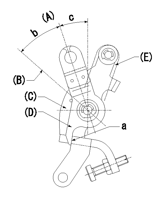
(A) Idle
(B) Full speed
(C) Base lever
(D) Accelerator lever
(E) Accelerator lever delivery position
1. Measure speed lever angle
(1)Measure the angle when the accelerator lever (D) contacted the base lever (C) at a.
----------
----------
b=(42deg)+-3deg c=18.5deg+-5deg
----------
----------
b=(42deg)+-3deg c=18.5deg+-5deg
0000001601 LEVER

(A) Accelerator lever stopper bolt
(B) Link
(c) Nut
(D) Lever
(E) Pin
(f) lever
(G) Stopper bolt
(H) Return spring
(J) Pin (E) contacts lever.
(K) Load sensor terminal
(1)Black
(2)Blue-yellow
(3)Blue-red
Setting the accelerator lever angle, load sensor adjustment
1. Accelerator lever setting method
(1)Position the speed lever against the idle stopper bolt and fix.
(2)Screw in the accelerator lever stopper bolt (A) and back off the stopper bolt (A) from the position where the accelerator lever pin contacts the speed lever and set. (Gap: approx. 1 mm)
Tightening torque: 4.9~7 N.m {0.5~0.7 kgf.m}
2. Load sensor adjustment (See fig 1)
(1)Load sensor output measuring circuit
Apply DC5+-0.01V to the load sensor terminals and measure the output voltage.
(2)Load sensor output adjustment procedure
Hold the speed lever against the full side stopper bolt and fix. Adjust the load sensor output voltage to VF = 0.417+-0.1 V using the link (B) and then fix temporarily using nut (C).
Turn the speed lever from the idle side to the full side and confirm that output voltage VF = 0.417+-0.1 V is obtained. Confirm several times and then fix using nut (C).
Tightening torque: 3.4~4.9 N.m {0.35~0.5 kgf.m}
3. Setting the step motor's idle side stopper bolt
After adjustment in previous 1 and 2, position speed lever against idle stopper bolt and fix. Then, screw in stopper bolt G until step motor lever D's pin E contacts lever F. Back off 10+2 deg (approx. 3.5 mm) from this position and fix G. (See fig. 3)
4. Speed lever return confirmation
(1)Remove return spring (H) and confirm that the speed lever is returned to the idle position by the torsion spring.
(2)Reinstall the return spring (H) in its original position.
----------
----------
----------
----------
Timing setting

(1)Pump vertical direction
(2)Position of timer's tooth at No 1 cylinder's beginning of injection
(3)B.T.D.C.: aa
(4)-
----------
aa=10deg
----------
a=(3deg)
----------
aa=10deg
----------
a=(3deg)
Information:
Illustration 62 g02807941
Remove the plug
Remove plug (2) .
Illustration 63 g02807956
Set speed by turning adjusting screw
Adjust speed. If Ng exceeds TMI specifications, tighten the adjusting screw. If Ng is less than the specified value, loosen the adjusting screw.
Illustration 64 g02807957
Adjust the maximum-speed stopper bolt
Adjust the maximum-speed stopper bolt until the speed at the start of high-speed control is Nf.
Check that the no-load maximum speed is Ng (described in Step 1). Continue adjustment until the specified value is obtained.
Illustration 65 g02807958
Increase pump speed to make sure that the control rack position reaches Ra.
Illustration 66 g02807959
Full-load Adjustment
Illustration 67 g02807997
Install the cover and adjust full-load stopper bolt
Install cover (3) on governor using bolts and lockwashers (2). Use caution when installing the cover to make sure that the O-ring seal is in the seal groove.
Illustration 68 g02807999
Position the control lever at maximum-speed position.
Adjust full-load stopper bolt (1) to the f"ull-load fuel injection quantity" position. See TMI for the specifications (Point A).
Install cap.Control Lever Angle Measurement
Illustration 69 g02808016
Measuring control lever angle at the "full-speed" and "idling" positions.
Measuring the control lever angle at the "idling" and "full" positions.
If the angle is not as specified by TMI, replace the shifters shim. If the control lever is positioned toward the "full" position, replace the shifters shim with a thicker one. When control lever is toward the "idling" position, replace the shim with a thinner one.Check Starting Delivery
Illustration 70 g02808018
Remove measurement adapter
Remove measurement adapter (1) .
Illustration 71 g02808038
Cap must be installed to check delivery rate
Install cap (2) .
Run pump at speed specified in TMI.
Check delivery rate with specifications listed in TMI.
Stop pump rotation.
Illustration 72 g02808058
Adjusting screw for setting fuel flow
If delivery rate does not meet TMI specifications, remove cap (2), loosen lock nut, and adjust screw (3). Adjusting screw outward decreases fuel flow and inward increases fuel flow.
Install cap (2) and recheck delivery rate. Repeat Steps 2 through 6 until delivery rate is at specified value.Lockwiring Caps of Adjustment Screws
All adjustment stops (screws) that directly affect engine performance should be lockwired after adjustment. Do not readjust any stop without using the test stand can adversely affect the engine and engine performance.