Information injection-pump assembly
BOSCH
F 019 Z10 374
f019z10374
ZEXEL
101607-6150
1016076150

Rating:
Service parts 101607-6150 INJECTION-PUMP ASSEMBLY:
1.
_
6.
COUPLING PLATE
7.
COUPLING PLATE
8.
_
9.
_
10.
NOZZLE AND HOLDER ASSY
11.
Nozzle and Holder
12.
Open Pre:MPa(Kqf/cm2)
13.
NOZZLE-HOLDER
14.
NOZZLE
15.
NOZZLE SET
Cross reference number
BOSCH
F 019 Z10 374
f019z10374
ZEXEL
101607-6150
1016076150
Zexel num
Bosch num
Firm num
Name
Calibration Data:
Adjustment conditions
Test oil
1404 Test oil ISO4113 or {SAEJ967d}
1404 Test oil ISO4113 or {SAEJ967d}
Test oil temperature
degC
40
40
45
Nozzle and nozzle holder
105780-8140
Bosch type code
EF8511/9A
Nozzle
105780-0000
Bosch type code
DN12SD12T
Nozzle holder
105780-2080
Bosch type code
EF8511/9
Opening pressure
MPa
17.2
Opening pressure
kgf/cm2
175
Injection pipe
Outer diameter - inner diameter - length (mm) mm 6-2-600
Outer diameter - inner diameter - length (mm) mm 6-2-600
Overflow valve
131424-5520
Overflow valve opening pressure
kPa
255
221
289
Overflow valve opening pressure
kgf/cm2
2.6
2.25
2.95
Tester oil delivery pressure
kPa
157
157
157
Tester oil delivery pressure
kgf/cm2
1.6
1.6
1.6
Direction of rotation (viewed from drive side)
Left L
Left L
Injection timing adjustment
Direction of rotation (viewed from drive side)
Left L
Left L
Injection order
1-5-3-6-
2-4
Pre-stroke
mm
3.3
3.25
3.35
Beginning of injection position
Governor side NO.1
Governor side NO.1
Difference between angles 1
Cal 1-5 deg. 60 59.5 60.5
Cal 1-5 deg. 60 59.5 60.5
Difference between angles 2
Cal 1-3 deg. 120 119.5 120.5
Cal 1-3 deg. 120 119.5 120.5
Difference between angles 3
Cal 1-6 deg. 180 179.5 180.5
Cal 1-6 deg. 180 179.5 180.5
Difference between angles 4
Cyl.1-2 deg. 240 239.5 240.5
Cyl.1-2 deg. 240 239.5 240.5
Difference between angles 5
Cal 1-4 deg. 300 299.5 300.5
Cal 1-4 deg. 300 299.5 300.5
Injection quantity adjustment
Adjusting point
-
Rack position
11.2
Pump speed
r/min
850
850
850
Each cylinder's injection qty
mm3/st.
57.7
56
59.4
Basic
*
Fixing the rack
*
Standard for adjustment of the maximum variation between cylinders
*
Injection quantity adjustment_02
Adjusting point
H
Rack position
9.5+-0.5
Pump speed
r/min
275
275
275
Each cylinder's injection qty
mm3/st.
13.7
11.6
15.8
Fixing the rack
*
Standard for adjustment of the maximum variation between cylinders
*
Injection quantity adjustment_03
Adjusting point
A
Rack position
R1(11.2)
Pump speed
r/min
850
850
850
Average injection quantity
mm3/st.
57.7
56.7
58.7
Basic
*
Fixing the lever
*
Injection quantity adjustment_04
Adjusting point
B
Rack position
R1+0.1
Pump speed
r/min
1450
1450
1450
Average injection quantity
mm3/st.
72.6
68.6
76.6
Fixing the lever
*
Injection quantity adjustment_05
Adjusting point
C
Rack position
R1+0.8
Pump speed
r/min
500
500
500
Average injection quantity
mm3/st.
59.7
55.7
63.7
Fixing the lever
*
Injection quantity adjustment_06
Adjusting point
D
Rack position
R1+1.25
Pump speed
r/min
300
300
300
Average injection quantity
mm3/st.
57.1
53.1
61.1
Fixing the lever
*
Injection quantity adjustment_07
Adjusting point
I
Rack position
-
Pump speed
r/min
100
100
100
Average injection quantity
mm3/st.
140
130
150
Fixing the lever
*
Rack limit
*
Timer adjustment
Pump speed
r/min
1250--
Advance angle
deg.
0
0
0
Remarks
Start
Start
Timer adjustment_02
Pump speed
r/min
1200
Advance angle
deg.
0.5
Timer adjustment_03
Pump speed
r/min
1400
Advance angle
deg.
5
4.5
5.5
Remarks
Finish
Finish
Test data Ex:
Governor adjustment
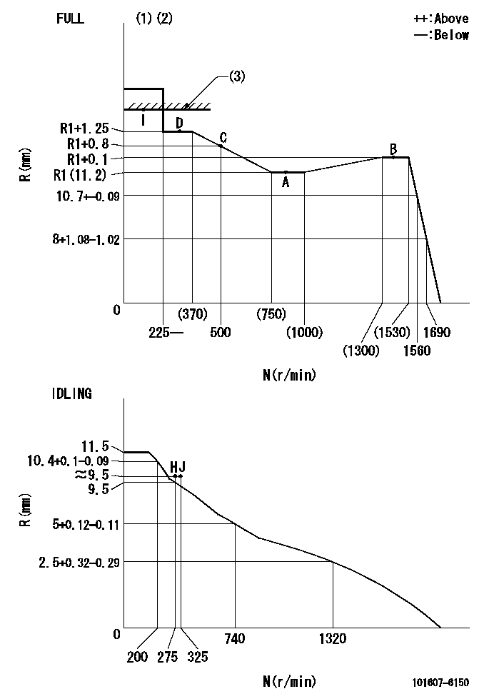
N:Pump speed
R:Rack position (mm)
(1)Torque cam stamping: T1
(2)Tolerance for racks not indicated: +-0.05mm.
(3)RACK LIMIT
----------
T1=G81
----------
----------
T1=G81
----------
Speed control lever angle
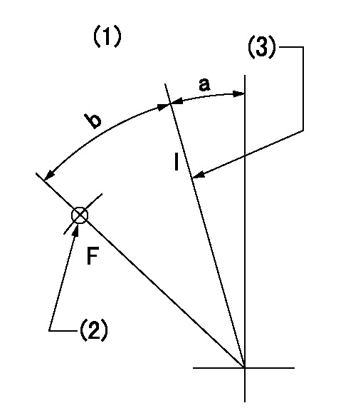
F:Full speed
I:Idle
(1)Accelerator lever
(2)Use the hole at R = aa
(3)Stopper bolt set position 'H'
----------
aa=29mm
----------
a=18.5deg+-5deg b=(39deg)+-3deg
----------
aa=29mm
----------
a=18.5deg+-5deg b=(39deg)+-3deg
Stop lever angle

N:Engine manufacturer's normal use
S:Stop the pump.
(1)Set the stopper bolt at pump speed = aa and rack position = bb (non-injection rack position). Confirm non-injection.
(2)After setting the stopper bolt, confirm non-injection at speed = cc. Rack position = actual (non-injection rack position).
(3)Rack position = approximately dd
(4)Free (at delivery)
(5)Use the hole above R = ee
----------
aa=1550r/min bb=7-0.5mm cc=275r/min dd=(16.8)mm ee=50mm
----------
a=36.5deg+-5deg b=(25deg) c=17deg+-5deg
----------
aa=1550r/min bb=7-0.5mm cc=275r/min dd=(16.8)mm ee=50mm
----------
a=36.5deg+-5deg b=(25deg) c=17deg+-5deg
0000001501 LEVER
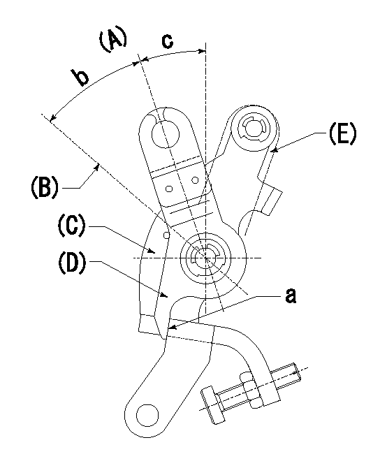
(A) Idle
(B) Full speed
(C) Base lever
(D) Accelerator lever
(E) Accelerator lever delivery position
1. Measure speed lever angle
(1)Measure the angle when the accelerator lever (D) contacted the base lever (C) at a.
----------
----------
b=(39deg)+-3deg c=18.5deg+-5deg
----------
----------
b=(39deg)+-3deg c=18.5deg+-5deg
0000001601 RACK SENSOR

V1:Supply voltage
V2f:Full side output voltage
V2i:Idle side output voltage
(A) Black
(B) Yellow
(C) Red
(D) Trimmer
(E): Shaft
(F) Nut
(G) Load lever
1. Load sensor adjustment
(1)Connect as shown in the above diagram and apply supply voltage V1.
(2)Hold the load lever (G) against the full side.
(3)Turn the shaft so that the voltage between (A) and (B) is V2.
(4)Hold the load lever (G) against the idle side.
(5)Adjust (D) so that the voltage between (A) and (B) is V2i.
(6)Repeat the above adjustments.
(7)Tighten the nut (F) at the point satisfying the standards.
(8)Hold the load lever against the full side stopper and the idle side stopper.
(9)At this time, confirm that the full side output voltage is V2f and the idle side output voltage is V2i.
----------
V1=3.57+-0.02V V2f=3+0.05V V2i=1+0.1V
----------
----------
V1=3.57+-0.02V V2f=3+0.05V V2i=1+0.1V
----------
0000001701 MICRO SWITCH
Adjust the bolt to obtain the following lever position when the micro-switch is OFF.
1. Microswitch adjustment (OPEN type)
Confirm with the lever angle at full.
(1)Speed N1
(2)Rack position Ra
----------
N1=1560r/min Ra=10.7+-0.1mm
----------
----------
N1=1560r/min Ra=10.7+-0.1mm
----------
Timing setting

(1)Pump vertical direction
(2)Position of timer's tooth at No 1 cylinder's beginning of injection
(3)B.T.D.C.: aa
(4)-
----------
aa=13deg
----------
a=(3deg)
----------
aa=13deg
----------
a=(3deg)
Information:
Use tool (E) in order to cut off the part of rivet (1) that has been peened. Remove rivet (1) from fuel injection control linkage (4) .
Illustration 13 g00702186
The 180-7951 Bushing Assembly Kit (F) Rack Control Shaft (G) Governor Link (4) Fuel Injection Control Linkage (7) 180-7952 Lever Bushing (8) 8L-5832 Hex Nut (9) 9X-8907 Hexagon Button Screw
Use the 180-7951 Bushing Assembly Kit in order to modify the linkage. Insert 9X-8907 Hexagon Button Screw (9) from the 180-7951 Bushing Assembly Kit into fuel injection control linkage (4). Refer to Illustration 13.
Apply 169-5464 Quick Cure Primer apply on the threads of 9X-8907 Hexagon Button Screw (9) and 8L-5832 Hex Nut (8). Allow the primer to dry. The Quick Cure Primer counteracts the effects of the Volatile Corrosion Inhibitor (VCI) paper that was used to package the parts.
Assemble 180-7952 Lever Bushing (7) on 9X-8907 Hexagon Button Screw (9). Refer to Illustration 13.
Apply the 154-9731 Thread Lock Compound on the threads of 9X-8907 Hexagon Button Screw (9) and 8L-5832 Hex Nut (8) .
Illustration 14 g00655322
Place 8L-5832 Hex Nut (8) on 9X-8907 Hexagon Button Screw (9). Tighten 8L-5832 Hex Nut (8) until hex nut (8) is snug. Tighten 8L-5832 Hex Nut (8) for an additional 180 degrees.
Do not let metal chips or pieces of the rivet fall into the engine.
Illustration 15 g00655325
Clean the fuel injection control linkage and clean the surfaces of the cylinder head that are adjacent to the fuel injection control linkage with shop solvent. Remove the towels and remove all debris very carefully.
Install the 180-7956 Clamp Assembly Kit . Refer to the "Installation Of The 180-7956 Clamp Assembly Kit " section of this publication.Installation Of The 180-7956 Clamp Assembly Kit
Note: The 180-7956 Clamp Assembly Kit is used for the former control linkages only.Note: If the 180-7956 Clamp Assembly Kit is installed, refer to ""Modification of the 128-9640 Injector Synchronization Fixture "".The 180-7956 Clamp Assembly Kit may be installed on the fuel injection control linkage. The 180-7956 Clamp Assembly Kit will increase the strength of the joint.
Illustration 16 g00655326
Install 183-9390 Spacer (10) on fuel injection control linkage (4). Refer to Illustration 16.
Apply 169-5464 Quick Cure Primer to the threaded hole in the 180-7954 Clamp (11). Apply 169-5464 Quick Cure Primer to the threads of screw (13). Allow the primer to dry. The Quick Cure Primer counteracts the effects of the Volatile Corrosion Inhibitor (VCI) paper that was used to package the parts.
Apply 154-9731 Thread Lock Compound to the threaded hole in the 180-7954 Clamp (11). Apply 154-9731 Thread Lock Compound to the threads of screw (13) of clamp assembly. Loosely assemble 180-7954 Clamp (11) and 180-7987 Clamp (12) on fuel injection control linkage (4). Refer to Illustration 16. Be sure that the rivet head or bushing (14) is fully engaged into the counterbore of the