Information injection-pump assembly
BOSCH
9 400 612 534
9400612534
ZEXEL
101607-1790
1016071790
Rating:
Service parts 101607-1790 INJECTION-PUMP ASSEMBLY:
1.
_
7.
COUPLING PLATE
8.
_
9.
_
11.
Nozzle and Holder
ME056371
12.
Open Pre:MPa(Kqf/cm2)
21.6{220}

15.
NOZZLE SET
Cross reference number
BOSCH
9 400 612 534
9400612534
ZEXEL
101607-1790
1016071790
Zexel num
Bosch num
Firm num
Name
Calibration Data:
Adjustment conditions
Test oil
1404 Test oil ISO4113 or {SAEJ967d}
1404 Test oil ISO4113 or {SAEJ967d}
Test oil temperature
degC
40
40
45
Nozzle and nozzle holder
105780-8140
Bosch type code
EF8511/9A
Nozzle
105780-0000
Bosch type code
DN12SD12T
Nozzle holder
105780-2080
Bosch type code
EF8511/9
Opening pressure
MPa
17.2
Opening pressure
kgf/cm2
175
Injection pipe
Outer diameter - inner diameter - length (mm) mm 6-2-600
Outer diameter - inner diameter - length (mm) mm 6-2-600
Overflow valve
131424-5120
Overflow valve opening pressure
kPa
255
221
289
Overflow valve opening pressure
kgf/cm2
2.6
2.25
2.95
Tester oil delivery pressure
kPa
157
157
157
Tester oil delivery pressure
kgf/cm2
1.6
1.6
1.6
Direction of rotation (viewed from drive side)
Right R
Right R
Injection timing adjustment
Direction of rotation (viewed from drive side)
Right R
Right R
Injection order
1-5-3-6-
2-4
Pre-stroke
mm
4.5
4.45
4.55
Beginning of injection position
Governor side NO.1
Governor side NO.1
Difference between angles 1
Cal 1-5 deg. 60 59.5 60.5
Cal 1-5 deg. 60 59.5 60.5
Difference between angles 2
Cal 1-3 deg. 120 119.5 120.5
Cal 1-3 deg. 120 119.5 120.5
Difference between angles 3
Cal 1-6 deg. 180 179.5 180.5
Cal 1-6 deg. 180 179.5 180.5
Difference between angles 4
Cyl.1-2 deg. 240 239.5 240.5
Cyl.1-2 deg. 240 239.5 240.5
Difference between angles 5
Cal 1-4 deg. 300 299.5 300.5
Cal 1-4 deg. 300 299.5 300.5
Injection quantity adjustment
Adjusting point
-
Rack position
9.6
Pump speed
r/min
700
700
700
Each cylinder's injection qty
mm3/st.
112
108.6
115.4
Basic
*
Fixing the rack
*
Standard for adjustment of the maximum variation between cylinders
*
Injection quantity adjustment_02
Adjusting point
C
Rack position
8+-0.5
Pump speed
r/min
225
225
225
Each cylinder's injection qty
mm3/st.
18.5
15.7
21.3
Fixing the rack
*
Standard for adjustment of the maximum variation between cylinders
*
Injection quantity adjustment_03
Adjusting point
A
Rack position
R1(9.6)
Pump speed
r/min
700
700
700
Average injection quantity
mm3/st.
112
111
113
Basic
*
Fixing the lever
*
Injection quantity adjustment_04
Adjusting point
B
Rack position
R1(9.6)
Pump speed
r/min
1100
1100
1100
Average injection quantity
mm3/st.
113.5
111
116
Difference in delivery
mm3/st.
9
9
9
Fixing the lever
*
Injection quantity adjustment_05
Adjusting point
E
Rack position
-
Pump speed
r/min
100
100
100
Average injection quantity
mm3/st.
140
120
160
Fixing the lever
*
Remarks
After startup boost setting
After startup boost setting
Timer adjustment
Pump speed
r/min
850--
Advance angle
deg.
0
0
0
Remarks
Start
Start
Timer adjustment_02
Pump speed
r/min
800
Advance angle
deg.
0.5
Timer adjustment_03
Pump speed
r/min
900
Advance angle
deg.
0.9
0.4
1.4
Timer adjustment_04
Pump speed
r/min
1150
Advance angle
deg.
3
2.5
3.5
Timer adjustment_05
Pump speed
r/min
-
Advance angle
deg.
4
4
5
Remarks
Measure the actual speed, stop
Measure the actual speed, stop
Test data Ex:
Governor adjustment
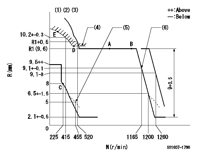
N:Pump speed
R:Rack position (mm)
(1)Lever ratio: RT
(2)Target shim dimension: TH
(3)Tolerance for racks not indicated: +-0.05mm.
(4)Excess fuel setting for starting: SXL
(5)Damper spring setting
(6)Set at delivery
----------
RT=1 TH=2.7mm SXL=R1+0.2mm
----------
----------
RT=1 TH=2.7mm SXL=R1+0.2mm
----------
Speed control lever angle

F:Full speed
----------
----------
a=(15deg)+-5deg
----------
----------
a=(15deg)+-5deg
0000000901
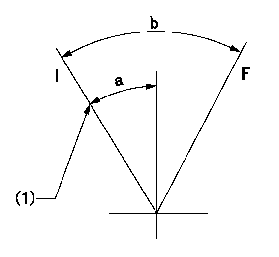
F:Full load
I:Idle
(1)Stopper bolt setting
----------
----------
a=24deg+-5deg b=27.5deg+-3deg
----------
----------
a=24deg+-5deg b=27.5deg+-3deg
Stop lever angle
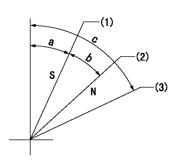
N:Pump normal
S:Stop the pump.
(1)Rack position = aa, stopper bolt setting
(2)Rack position bb
(3)Free (at delivery)
----------
aa=5.5-0.5mm bb=16mm
----------
a=12.5deg+5deg-7deg b=34deg+-5deg c=(66.5deg)
----------
aa=5.5-0.5mm bb=16mm
----------
a=12.5deg+5deg-7deg b=34deg+-5deg c=(66.5deg)
0000001501 TAMPER PROOF
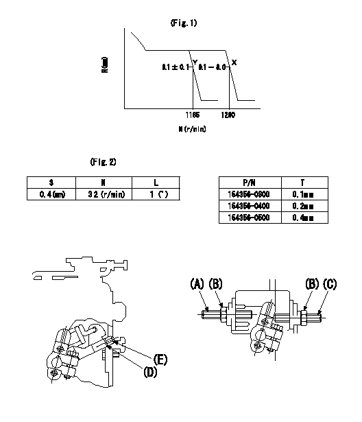
N:Pump speed (r/min)
R:Rack position (mm)
S:Shim thickness (1; mm)
L:Lever angle (deg)
T:Thickness (mm)
P/N: part number of shim
(A) Speed set bolt
Locknut B
Speed set bolt C
(d) Shim
(E) Screw
Tamper proof adjustment
(1)Adjustment standard
1. Tamperproof adjustment specifications are shown in figure 1.
(2)Adjustment procedure
1. Temporarily set with 4 shims (D; thickness = 0.4 mm) assembled.
2. Perform governor adjustment as described in the calibration data sheet.
3. At this time, confirm that the specified setting (point Y: 1165 r/min) can be obtained using the speed set bolt (A).
4-1 When specified setting can be obtained
4-1-1 Back off the speed set bolt (C).
4-1-2 Confirm that point X is satisfied when the speed set bolt (A) is further tightened.
4-2 When specified setting can be obtained
4-2-1 Repeat disassembly and confirm that the specified setting (point Y: 1165 r/min) can be obtained when a suitable number of shims (D) are removed.
4-2-2 As in 4-1 above, confirm that the point X is satisfied when the setting is increased.
4-2-3 Adjust after referring to figure 2 for the number of shims.
Reference: Screw (E) and the pump housing contact in 4-1 and 4-2 above.
5-1 After completing confirmation in (1), reset at the specified setting (point Y: 1165 r/min) using the speed set bolt (A) and (C).
5-2 fix using locknut (B) and finish adjustment.
----------
----------
----------
----------
0000001601 MICRO SWITCH
Adjustment of the micro-switch
Adjust the bolt to obtain the following lever position when the micro-switch is ON.
(1)Speed N1
(2)Rack position Ra
----------
N1=325r/min Ra=7.3+-0.1mm
----------
----------
N1=325r/min Ra=7.3+-0.1mm
----------
Timing setting

(1)Pump vertical direction
(2)Coupling's key groove position at No 1 cylinder's beginning of injection
(3)-
(4)-
----------
----------
a=(7deg)
----------
----------
a=(7deg)
Information:
Introduction
This Special Instruction contains the strap torquing procedure for the straps on the DEF tank.Read the entire Special Instruction. Understand the information before you perform any procedures. Strap Torquing Procedure
Illustration 1 g03354750
(1) Strap (2) Nut
Install strap (1) and torque nut (2) .Torque for nut (2) ... 11 1 N m (97 9 lb in)Note: If the strap has a hook or other non-adjustable fastener on one end, only the adjustment end is torqued during installation.Note: If both ends of the strap have adjustable fasteners, both ends should be torqued only once. Do not go back and forth when applying assembly torque. Torque the first side to specification, then ensure that the torque on the second side is at specifications. Do not go back and retorque the first side.