Information injection-pump assembly
BOSCH
9 400 615 633
9400615633
ZEXEL
101607-1670
1016071670
MITSUBISHI
ME047661
me047661

Rating:
Cross reference number
BOSCH
9 400 615 633
9400615633
ZEXEL
101607-1670
1016071670
MITSUBISHI
ME047661
me047661
Zexel num
Bosch num
Firm num
Name
101607-1670
9 400 615 633
ME047661 MITSUBISHI
INJECTION-PUMP ASSEMBLY
6D14T K
6D14T K
Calibration Data:
Adjustment conditions
Test oil
1404 Test oil ISO4113 or {SAEJ967d}
1404 Test oil ISO4113 or {SAEJ967d}
Test oil temperature
degC
40
40
45
Nozzle and nozzle holder
105780-8140
Bosch type code
EF8511/9A
Nozzle
105780-0000
Bosch type code
DN12SD12T
Nozzle holder
105780-2080
Bosch type code
EF8511/9
Opening pressure
MPa
17.2
Opening pressure
kgf/cm2
175
Injection pipe
Outer diameter - inner diameter - length (mm) mm 6-2-600
Outer diameter - inner diameter - length (mm) mm 6-2-600
Overflow valve
131424-5520
Overflow valve opening pressure
kPa
255
255
255
Overflow valve opening pressure
kgf/cm2
2.6
2.6
2.6
Tester oil delivery pressure
kPa
157
157
157
Tester oil delivery pressure
kgf/cm2
1.6
1.6
1.6
Direction of rotation (viewed from drive side)
Left L
Left L
Injection timing adjustment
Direction of rotation (viewed from drive side)
Left L
Left L
Injection order
1-5-3-6-
2-4
Pre-stroke
mm
3.3
3.25
3.35
Beginning of injection position
Governor side NO.1
Governor side NO.1
Difference between angles 1
Cal 1-5 deg. 60 59.5 60.5
Cal 1-5 deg. 60 59.5 60.5
Difference between angles 2
Cal 1-3 deg. 120 119.5 120.5
Cal 1-3 deg. 120 119.5 120.5
Difference between angles 3
Cal 1-6 deg. 180 179.5 180.5
Cal 1-6 deg. 180 179.5 180.5
Difference between angles 4
Cyl.1-2 deg. 240 239.5 240.5
Cyl.1-2 deg. 240 239.5 240.5
Difference between angles 5
Cal 1-4 deg. 300 299.5 300.5
Cal 1-4 deg. 300 299.5 300.5
Injection quantity adjustment
Adjusting point
A
Rack position
9.5
Pump speed
r/min
1100
1100
1100
Average injection quantity
mm3/st.
76.2
75.2
77.2
Max. variation between cylinders
%
0
-2.5
2.5
Basic
*
Fixing the lever
*
Injection quantity adjustment_02
Adjusting point
B
Rack position
7.6+-0.5
Pump speed
r/min
375
375
375
Average injection quantity
mm3/st.
9.7
8.2
11.2
Max. variation between cylinders
%
0
-15
15
Fixing the rack
*
Timer adjustment
Pump speed
r/min
1200++
Advance angle
deg.
0
0
0
Remarks
Do not advance until starting N = 1200.
Do not advance until starting N = 1200.
Timer adjustment_02
Pump speed
r/min
-
Advance angle
deg.
2
1.5
2.5
Remarks
Measure the actual speed, stop
Measure the actual speed, stop
Test data Ex:
Governor adjustment
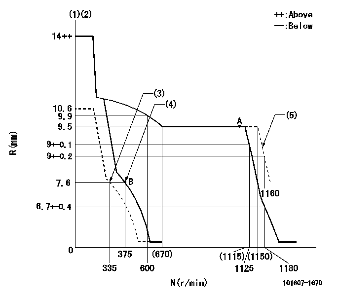
N:Pump speed
R:Rack position (mm)
(1)Target notch: K
(2)Tolerance for racks not indicated: +-0.05mm.
(3)Set idle sub-spring
(4)Main spring setting
(5)Set at delivery
----------
K=12
----------
----------
K=12
----------
Speed control lever angle
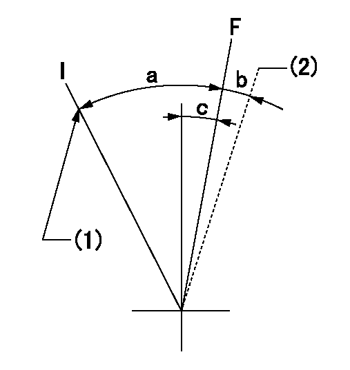
F:Full speed
I:Idle
(1)Stopper bolt setting
(2)At delivery
----------
----------
a=23deg+-5deg b=(2deg) c=7deg+-5deg
----------
----------
a=23deg+-5deg b=(2deg) c=7deg+-5deg
Stop lever angle
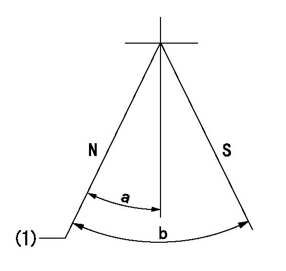
N:Pump normal
S:Stop the pump.
(1)Normal
----------
----------
a=26deg+-5deg b=53deg+-5deg
----------
----------
a=26deg+-5deg b=53deg+-5deg
Timing setting

(1)Pump vertical direction
(2)Position of gear mark '2' at No 1 cylinder's beginning of injection
(3)B.T.D.C.: aa
(4)-
----------
aa=18deg
----------
a=(80deg)
----------
aa=18deg
----------
a=(80deg)
Information:
Illustration 9 g00293067
(5) Air shutoff solenoid that is mounted in the air intake pipe.
Illustration 10 g00281839
Air Shutoff (Typical Example)
Table 2
(1) Air transfer pipe. (5) Air shutoff solenoid.
(2) Valve assembly. (6) O-ring seal.
(3) Shutoff shaft. (7) Diode assembly.
(4) Governor control shaft. The air shutoff solenoid (5) is located in the air inlet system on the top of the engine. When the air shutoff solenoid (ASOS) is activated, the inlet air to the engine is mechanically shut off. The ASOS can be only activated in two ways:
The ASOS is activated by the overspeed switch (OS).
The ASOS is activated by the emergency stop switch (ES).Fuel Shutoff Solenoid (FSOS)
Illustration 11 g00281970
Fuel Solenoid (Typical Example) (1) Diode assembly. (2) Spring. (3) Governor drive. (4) Fuel solenoid. (5) Shaft.
Illustration 12 g00293070
(4) Fuel shutoff solenoid (FSOS) that is mounted on the governor.The fuel shutoff solenoid (FSOS) (4) is located on the governor or on the fuel injection pump of the engine.When the FSOS is energized, the spring (2) and the shaft (5) will cause the fuel rack to move directly or the fuel rack will move through governor drive (3) to the FUEL OFF position. The FSOS remains energized until the time delay relay causes the circuit of the FSOS to de-energize.Time Delay Relay (TD)
Illustration 13 g00281989
4W-8471 Time Delay Relay The time delay relay is an ON/OFF switch which has two controls. When the electric protection system is energized, one control will immediately activate the time delay relay. The other control will activate a relay after a delay of 9 seconds when a continuous signal is received. The time delay relay has a 70 second OFF delay after the signal is removed from both the input terminal (TD-1) and the input terminal (TD-2).The time delay relay is mounted in the junction box.2301AElectric Governor Control
Illustration 14 g00293071
(1) 2301A Electric Governor Speed Control
Illustration 15 g00293069
Electric governor actuator (EGA) (2) and fuel shutoff solenoid (FSOS) (3). These components are mounted on the top of the engine.The 2301A Electric Governor Control system consists of the following components:
2301A Control
Actuator (EGA)
Magnetic pickup (MPU)The 2301A Electric Governor Control system provides precision engine speed control. The 2301A Control constantly monitors the engine rpm. The control makes necessary corrections to the engine fuel setting through an actuator connected to the fuel system.The engine rpm is measured by the magnetic pickup (MU). The magnetic pickup makes an AC voltage that is sent to the 2301A Control. The 2301A Control then sends a DC voltage signal to the actuator in order to adjust the fuel flow.The actuator changes the electrical signal from the 2301A Control to a mechanical output. The mechanical output of the actuator causes the linkage from the actuator to move the fuel rack. This will increase the flow of fuel to the engine or this will decrease the flow of fuel to the engine. For example, if the engine speed is more than the speed setting, the 2301A Control will decrease the voltage output which
Have questions with 101607-1670?
Group cross 101607-1670 ZEXEL
Mitsubishi
Mitsubishi
101607-1670
9 400 615 633
ME047661
INJECTION-PUMP ASSEMBLY
6D14T
6D14T