Information injection-pump assembly
ZEXEL
101607-1630
1016071630
MITSUBISHI
ME056901
me056901
Rating:
Service parts 101607-1630 INJECTION-PUMP ASSEMBLY:
1.
_
7.
COUPLING PLATE
8.
_
9.
_
11.
Nozzle and Holder
ME056371
12.
Open Pre:MPa(Kqf/cm2)
21.6{220}

15.
NOZZLE SET
Cross reference number
ZEXEL
101607-1630
1016071630
MITSUBISHI
ME056901
me056901
Zexel num
Bosch num
Firm num
Name
101607-1630
ME056901 MITSUBISHI
INJECTION-PUMP ASSEMBLY
6D22 * K
6D22 * K
Calibration Data:
Adjustment conditions
Test oil
1404 Test oil ISO4113 or {SAEJ967d}
1404 Test oil ISO4113 or {SAEJ967d}
Test oil temperature
degC
40
40
45
Nozzle and nozzle holder
105780-8140
Bosch type code
EF8511/9A
Nozzle
105780-0000
Bosch type code
DN12SD12T
Nozzle holder
105780-2080
Bosch type code
EF8511/9
Opening pressure
MPa
17.2
Opening pressure
kgf/cm2
175
Injection pipe
Outer diameter - inner diameter - length (mm) mm 6-2-600
Outer diameter - inner diameter - length (mm) mm 6-2-600
Overflow valve
131424-5120
Overflow valve opening pressure
kPa
255
221
289
Overflow valve opening pressure
kgf/cm2
2.6
2.25
2.95
Tester oil delivery pressure
kPa
157
157
157
Tester oil delivery pressure
kgf/cm2
1.6
1.6
1.6
Direction of rotation (viewed from drive side)
Right R
Right R
Injection timing adjustment
Direction of rotation (viewed from drive side)
Right R
Right R
Injection order
1-5-3-6-
2-4
Pre-stroke
mm
4.5
4.45
4.55
Beginning of injection position
Governor side NO.1
Governor side NO.1
Difference between angles 1
Cal 1-5 deg. 60 59.5 60.5
Cal 1-5 deg. 60 59.5 60.5
Difference between angles 2
Cal 1-3 deg. 120 119.5 120.5
Cal 1-3 deg. 120 119.5 120.5
Difference between angles 3
Cal 1-6 deg. 180 179.5 180.5
Cal 1-6 deg. 180 179.5 180.5
Difference between angles 4
Cyl.1-2 deg. 240 239.5 240.5
Cyl.1-2 deg. 240 239.5 240.5
Difference between angles 5
Cal 1-4 deg. 300 299.5 300.5
Cal 1-4 deg. 300 299.5 300.5
Injection quantity adjustment
Adjusting point
-
Rack position
11.4
Pump speed
r/min
700
700
700
Each cylinder's injection qty
mm3/st.
112
108.6
115.4
Basic
*
Fixing the rack
*
Standard for adjustment of the maximum variation between cylinders
*
Injection quantity adjustment_02
Adjusting point
H
Rack position
9.5+-0.5
Pump speed
r/min
225
225
225
Each cylinder's injection qty
mm3/st.
18.5
15.7
21.3
Fixing the rack
*
Standard for adjustment of the maximum variation between cylinders
*
Injection quantity adjustment_03
Adjusting point
A
Rack position
R1(11.4)
Pump speed
r/min
700
700
700
Average injection quantity
mm3/st.
112
111
113
Basic
*
Fixing the lever
*
Injection quantity adjustment_04
Adjusting point
B
Rack position
R1+0.1
Pump speed
r/min
1075
1075
1075
Average injection quantity
mm3/st.
113.5
109.5
117.5
Difference in delivery
mm3/st.
9
9
9
Fixing the lever
*
Injection quantity adjustment_05
Adjusting point
I
Rack position
-
Pump speed
r/min
100
100
100
Average injection quantity
mm3/st.
140
120
160
Fixing the lever
*
Timer adjustment
Pump speed
r/min
850--
Advance angle
deg.
0
0
0
Remarks
Start
Start
Timer adjustment_02
Pump speed
r/min
800
Advance angle
deg.
0.5
Timer adjustment_03
Pump speed
r/min
1000
Advance angle
deg.
0.9
0.4
1.4
Timer adjustment_04
Pump speed
r/min
1075
Remarks
Measure the actual advance angle.
Measure the actual advance angle.
Timer adjustment_05
Pump speed
r/min
-
Advance angle
deg.
4
4
5
Remarks
Measure the actual speed, stop
Measure the actual speed, stop
Test data Ex:
Governor adjustment
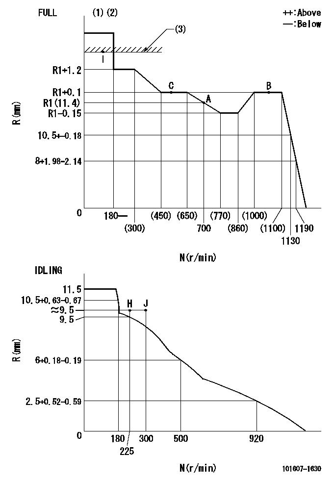
N:Pump speed
R:Rack position (mm)
(1)Torque cam stamping: T1
(2)Tolerance for racks not indicated: +-0.05mm.
(3)RACK LIMIT
----------
T1=D46
----------
----------
T1=D46
----------
Speed control lever angle

F:Full speed
I:Idle
(1)Stopper bolt set position 'H'
----------
----------
a=18.5deg+-5deg b=(42deg)+-3deg
----------
----------
a=18.5deg+-5deg b=(42deg)+-3deg
Stop lever angle
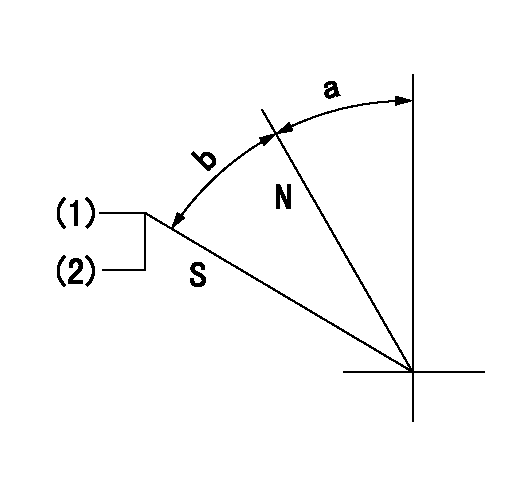
N:Pump normal
S:Stop the pump.
(1)Set the stopper bolt at pump speed = aa and rack position = bb (non-injection rack position). Confirm non-injection.
(2)After setting the stopper bolt, confirm non-injection at speed cc. Rack position = dd (non-injection rack position).
----------
aa=1075r/min bb=(6.5)-0.5mm cc=225r/min dd=(6.5)-0.5mm
----------
a=11.5deg+-5deg b=(27deg)+-5deg
----------
aa=1075r/min bb=(6.5)-0.5mm cc=225r/min dd=(6.5)-0.5mm
----------
a=11.5deg+-5deg b=(27deg)+-5deg
0000001501 MICRO SWITCH
Adjustment of the micro-switch
Adjust the bolt to obtain the following lever position when the micro-switch is ON.
(1)Speed N1
(2)Rack position Ra
----------
N1=325r/min Ra=8.8+-0.1mm
----------
----------
N1=325r/min Ra=8.8+-0.1mm
----------
Timing setting

(1)Pump vertical direction
(2)Coupling's key groove position at No 1 cylinder's beginning of injection
(3)-
(4)-
----------
----------
a=(7deg)
----------
----------
a=(7deg)
Information:
When using Cat ELC, do not use conventional SCAs, or, if equipped, SCA maintenance elements. In order to avoid SCA contamination of an ELC system, remove the SCA element base and plug off or bypass the coolant lines.
Cat ELC Cooling System Cleaning
Note: If the cooling system is already using Cat ELC, cleaning agents are not required at the specified coolant change interval. Cleaning agents are only required if the system has been contaminated by the addition of some other type of coolant or by cooling system damage.Clean water is the only cleaning agent that is required when Cat ELC is drained from a properly maintained cooling system.After the cooling system is drained and after the cooling system is refilled, operate the engine while the cooling system filler cap is removed. Operate the engine until the coolant level reaches the normal operating temperature and until the coolant level stabilizes. As needed, add the coolant mixture in order to fill the system to the proper level.Recycling Cat ELC
Cat ELC can be recycled into conventional coolants. The drained coolant mixture can be distilled in order to remove the ethylene glycol and the water. The ethylene glycol and the water can be reused. The distilled material does not contain the additives that are classified as either Cat ELC or Cat DEAC. Consult your Cat dealer for more information. Recycled coolants should meet the most current revision level of "ASTM D6210".Changing to Cat ELC
To change from heavy-duty coolant/antifreeze to the Cat ELC, perform the following steps:
Care must be taken to ensure that fluids are contained during performance of inspection, maintenance, testing, adjusting and repair of the product. Be prepared to collect the fluid with suitable containers before opening any compartment or disassembling any component containing fluids.Refer to Special Publication, NENG2500, "Caterpillar Dealer Service Tool Catalog" and to Special Publication, PECJ0003, "Cat Shop Supplies and Tools" for tools and supplies suitable to collect and contain fluids on Cat products.Dispose of all fluids according to applicable regulations and mandates.
Drain the coolant into a suitable container.
Dispose of the coolant according to local regulations.
If equipped, remove the empty SCA maintenance element and remove the element base. Plug the coolant lines or bypass the coolant lines.
Do not leave an empty SCA maintenance element on a system that is filled with Cat ELC.The element housing may corrode and leak causing an engine failure.Remove the SCA element base and plug off or by-pass the coolant lines.
Flush the system with clean water in order to remove any debris.
Use Cat Quick Flush Cooling System Cleaner for cooling systems in order to clean the system. Cat Quick Flush Cooling System Cleaner is available in various sizes. Part numbers are 4C-4609 ( 0.5 L (0.125 US gal)) through 4C-4613 ( 208.2 L (55 US gal)). Follow the instructions on the label using a 6-10% concentration of cleaner in water.
Drain the cleaner into a suitable container. Flush the cooling system with clean water. Note: Deposits that remain in the system may be loosened and removed
Have questions with 101607-1630?
Group cross 101607-1630 ZEXEL
Mitsubishi
101607-1630
ME056901
INJECTION-PUMP ASSEMBLY
6D22
6D22