Information injection-pump assembly
BOSCH
9 400 615 623
9400615623
ZEXEL
101607-1561
1016071561
MITSUBISHI
ME086676
me086676
Rating:
Service parts 101607-1561 INJECTION-PUMP ASSEMBLY:
1.
_
6.
COUPLING PLATE
7.
COUPLING PLATE
8.
_
9.
_
11.
Nozzle and Holder
ME086575
12.
Open Pre:MPa(Kqf/cm2)
17.7{180}
15.
NOZZLE SET
Include in #1:
101607-1561
as INJECTION-PUMP ASSEMBLY
Include in #2:
104746-6622
as _
Cross reference number
BOSCH
9 400 615 623
9400615623
ZEXEL
101607-1561
1016071561
MITSUBISHI
ME086676
me086676
Zexel num
Bosch num
Firm num
Name
101607-1561
9 400 615 623
ME086676 MITSUBISHI
INJECTION-PUMP ASSEMBLY
6D31 * K 14BE INJECTION PUMP ASSY PE6A PE
6D31 * K 14BE INJECTION PUMP ASSY PE6A PE
Calibration Data:
Adjustment conditions
Test oil
1404 Test oil ISO4113 or {SAEJ967d}
1404 Test oil ISO4113 or {SAEJ967d}
Test oil temperature
degC
40
40
45
Nozzle and nozzle holder
105780-8140
Bosch type code
EF8511/9A
Nozzle
105780-0000
Bosch type code
DN12SD12T
Nozzle holder
105780-2080
Bosch type code
EF8511/9
Opening pressure
MPa
17.2
Opening pressure
kgf/cm2
175
Injection pipe
Outer diameter - inner diameter - length (mm) mm 6-2-600
Outer diameter - inner diameter - length (mm) mm 6-2-600
Overflow valve
131424-6720
Overflow valve opening pressure
kPa
191
157
225
Overflow valve opening pressure
kgf/cm2
1.95
1.6
2.3
Tester oil delivery pressure
kPa
157
157
157
Tester oil delivery pressure
kgf/cm2
1.6
1.6
1.6
Direction of rotation (viewed from drive side)
Right R
Right R
Injection timing adjustment
Direction of rotation (viewed from drive side)
Right R
Right R
Injection order
1-5-3-6-
2-4
Pre-stroke
mm
3.6
3.55
3.65
Beginning of injection position
Drive side NO.1
Drive side NO.1
Difference between angles 1
Cal 1-5 deg. 60 59.5 60.5
Cal 1-5 deg. 60 59.5 60.5
Difference between angles 2
Cal 1-3 deg. 120 119.5 120.5
Cal 1-3 deg. 120 119.5 120.5
Difference between angles 3
Cal 1-6 deg. 180 179.5 180.5
Cal 1-6 deg. 180 179.5 180.5
Difference between angles 4
Cyl.1-2 deg. 240 239.5 240.5
Cyl.1-2 deg. 240 239.5 240.5
Difference between angles 5
Cal 1-4 deg. 300 299.5 300.5
Cal 1-4 deg. 300 299.5 300.5
Injection quantity adjustment
Adjusting point
-
Rack position
10.1
Pump speed
r/min
1000
1000
1000
Average injection quantity
mm3/st.
39.2
37.6
40.8
Max. variation between cylinders
%
0
-2.5
2.5
Basic
*
Fixing the rack
*
Standard for adjustment of the maximum variation between cylinders
*
Injection quantity adjustment_02
Adjusting point
H
Rack position
9.5+-0.5
Pump speed
r/min
300
300
300
Average injection quantity
mm3/st.
8
6.7
9.3
Max. variation between cylinders
%
0
-10
10
Fixing the rack
*
Standard for adjustment of the maximum variation between cylinders
*
Injection quantity adjustment_03
Adjusting point
A
Rack position
R1(10.1)
Pump speed
r/min
1000
1000
1000
Average injection quantity
mm3/st.
39.2
38.2
40.2
Basic
*
Fixing the lever
*
Injection quantity adjustment_04
Adjusting point
B
Rack position
R1+0.1
Pump speed
r/min
1600
1600
1600
Average injection quantity
mm3/st.
44.2
40.2
48.2
Fixing the lever
*
Injection quantity adjustment_05
Adjusting point
C
Rack position
R1+0.45
Pump speed
r/min
650
650
650
Average injection quantity
mm3/st.
39.6
35.6
43.6
Fixing the lever
*
Injection quantity adjustment_06
Adjusting point
D
Rack position
R1+0.85
Pump speed
r/min
500
500
500
Average injection quantity
mm3/st.
34.3
30.3
38.3
Fixing the lever
*
Injection quantity adjustment_07
Adjusting point
I
Rack position
-
Pump speed
r/min
100
100
100
Average injection quantity
mm3/st.
90
90
95
Fixing the lever
*
Rack limit
*
Timer adjustment
Pump speed
r/min
1150--
Advance angle
deg.
0
0
0
Remarks
Start
Start
Timer adjustment_02
Pump speed
r/min
1100
Advance angle
deg.
0.5
Timer adjustment_03
Pump speed
r/min
1600
Advance angle
deg.
5
4.5
5.5
Remarks
Finish
Finish
Test data Ex:
Governor adjustment
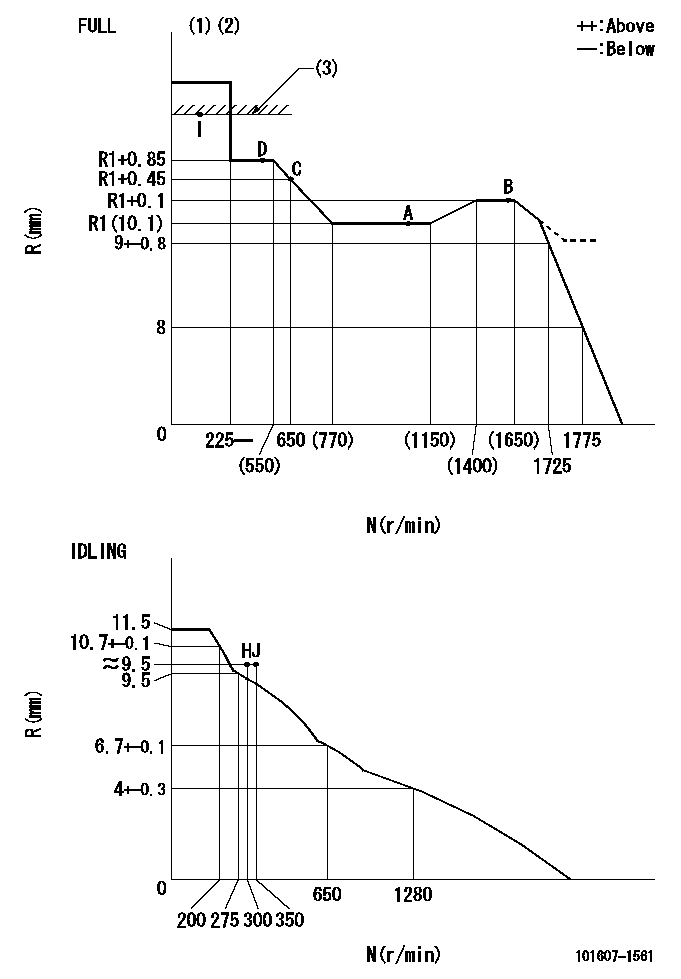
N:Pump speed
R:Rack position (mm)
(1)Torque cam stamping: T1
(2)Tolerance for racks not indicated: +-0.05mm.
(3)RACK LIMIT
----------
T1=F66
----------
----------
T1=F66
----------
Speed control lever angle

F:Full speed
I:Idle
(1)Use the hole at R = aa
(2)Stopper bolt set position 'H'
----------
aa=40mm
----------
a=26deg+-5deg b=37deg+-3deg
----------
aa=40mm
----------
a=26deg+-5deg b=37deg+-3deg
Stop lever angle

N:Engine manufacturer's normal use
S:Stop the pump.
(1)Free (at shipping)
(2)Use the hole at R = aa
(3)Rack position corresponding to bb
(4)Set the stopper bolt so that speed = cc and rack position = dd.
(5)After setting the stopper bolt, confirm non-injection at speed ee. (Rack position = ff or less)
----------
aa=40mm bb=16mm cc=1700r/min dd=6.5-0.5mm ee=275r/min ff=8mm
----------
a=8deg+-5deg b=15deg+-5deg c=25deg+-5deg
----------
aa=40mm bb=16mm cc=1700r/min dd=6.5-0.5mm ee=275r/min ff=8mm
----------
a=8deg+-5deg b=15deg+-5deg c=25deg+-5deg
Timing setting

(1)Pump vertical direction
(2)Position of timer's tooth at No 1 cylinder's beginning of injection
(3)B.T.D.C.: aa
(4)-
----------
aa=12deg
----------
a=(2deg)
----------
aa=12deg
----------
a=(2deg)
Information:
PROBLEM
The existing Diesel Oxidation Catalyst may develop a crack on the back plate end cap weld to the housing on certain 3512E Petroleum Engines.
AFFECTED PRODUCT
Model Identification Number
3512E SK300113-00249
SK500129-00592
PARTS NEEDED
Qty
Part Number Description
2 3031968 GASKET
4 3460335 CLAMP-BAND
1 4220219 GASKET-EXHAUST
1 5267934 MODULE AR-EXH
In order to allow equitable parts availability to all participating dealers, please limit your initial parts order to not exceed 1% of dealership population. This is an initial order recommendation only, and the ultimate responsibility for ordering the total number of parts needed to satisfy the program lies with the dealer.
ACTION REQUIRED
If the crack is 5mm wide or 6 inches long or larger then replace the Diesel Oxidation Catalyst.
Refer to Disassembly and Assembly, KENR8163, "Catalytic Converter - Remove and Install".
SERVICE CLAIM ALLOWANCES
Product smu/age whichever comes first Caterpillar Dealer Suggested Customer Suggested
Parts % Labor Hrs% Parts % Labor Hrs% Parts % Labor Hrs%
0-5000 hrs,
0-36 mo 100.0% 100.0% 0.0% 0.0% 0.0% 0.0%
5001-7500 hrs,
37-48 mo 75.0% 75.0% 0.0% 0.0% 25.0% 25.0%
7501-12000 hrs,
49-60 mo 50.0% 50.0% 0.0% 0.0% 50.0% 50.0%
12001-17500 hrs,
61-72 mo 25.0% 25.0% 0.0% 0.0% 75.0% 75.0%
This is a 6.0-hour job
If there has been a previous repair, part age/hours will apply. Retain a copy of the previous repair invoice in the dealer's records for audit purposes, and specify repair date and machine hours in the "Additional Comments" section of the warranty claim.
PARTS DISPOSITION
Handle the parts in accordance with your Warranty Bulletin on warranty parts handling.
Have questions with 101607-1561?
Group cross 101607-1561 ZEXEL
Mitsubishi
Mitsubishi
Mitsubishi
Mitsubishi
Mitsubishi
101607-1561
9 400 615 623
ME086676
INJECTION-PUMP ASSEMBLY
6D31
6D31