Information injection-pump assembly
BOSCH
F 019 Z10 836
f019z10836
ZEXEL
101607-1560
1016071560
Rating:
Service parts 101607-1560 INJECTION-PUMP ASSEMBLY:
1.
_
6.
COUPLING PLATE
7.
COUPLING PLATE
8.
_
9.
_
11.
Nozzle and Holder
ME086575
12.
Open Pre:MPa(Kqf/cm2)
17.7(180)
15.
NOZZLE SET
Include in #1:
101607-1560
as INJECTION-PUMP ASSEMBLY
Include in #2:
104746-6620
as _
Cross reference number
BOSCH
F 019 Z10 836
f019z10836
ZEXEL
101607-1560
1016071560
Zexel num
Bosch num
Firm num
Name
Calibration Data:
Adjustment conditions
Test oil
1404 Test oil ISO4113 or {SAEJ967d}
1404 Test oil ISO4113 or {SAEJ967d}
Test oil temperature
degC
40
40
45
Nozzle and nozzle holder
105780-8140
Bosch type code
EF8511/9A
Nozzle
105780-0000
Bosch type code
DN12SD12T
Nozzle holder
105780-2080
Bosch type code
EF8511/9
Opening pressure
MPa
17.2
Opening pressure
kgf/cm2
175
Injection pipe
Outer diameter - inner diameter - length (mm) mm 6-2-600
Outer diameter - inner diameter - length (mm) mm 6-2-600
Overflow valve
131424-6720
Overflow valve opening pressure
kPa
191
157
225
Overflow valve opening pressure
kgf/cm2
1.95
1.6
2.3
Tester oil delivery pressure
kPa
157
157
157
Tester oil delivery pressure
kgf/cm2
1.6
1.6
1.6
Direction of rotation (viewed from drive side)
Right R
Right R
Injection timing adjustment
Direction of rotation (viewed from drive side)
Right R
Right R
Injection order
1-5-3-6-
2-4
Pre-stroke
mm
3.6
3.55
3.65
Beginning of injection position
Drive side NO.1
Drive side NO.1
Difference between angles 1
Cal 1-5 deg. 60 59.5 60.5
Cal 1-5 deg. 60 59.5 60.5
Difference between angles 2
Cal 1-3 deg. 120 119.5 120.5
Cal 1-3 deg. 120 119.5 120.5
Difference between angles 3
Cal 1-6 deg. 180 179.5 180.5
Cal 1-6 deg. 180 179.5 180.5
Difference between angles 4
Cyl.1-2 deg. 240 239.5 240.5
Cyl.1-2 deg. 240 239.5 240.5
Difference between angles 5
Cal 1-4 deg. 300 299.5 300.5
Cal 1-4 deg. 300 299.5 300.5
Injection quantity adjustment
Adjusting point
-
Rack position
10.3
Pump speed
r/min
1000
1000
1000
Average injection quantity
mm3/st.
41.1
39.5
42.7
Max. variation between cylinders
%
0
-2.5
2.5
Basic
*
Fixing the rack
*
Standard for adjustment of the maximum variation between cylinders
*
Injection quantity adjustment_02
Adjusting point
H
Rack position
9.5+-0.5
Pump speed
r/min
275
275
275
Average injection quantity
mm3/st.
8.3
7
9.6
Max. variation between cylinders
%
0
-10
10
Fixing the rack
*
Standard for adjustment of the maximum variation between cylinders
*
Injection quantity adjustment_03
Adjusting point
A
Rack position
R1(10.3)
Pump speed
r/min
1000
1000
1000
Average injection quantity
mm3/st.
41.1
40.1
42.1
Basic
*
Fixing the lever
*
Injection quantity adjustment_04
Adjusting point
B
Rack position
R1+0.1
Pump speed
r/min
1600
1600
1600
Average injection quantity
mm3/st.
46.6
42.6
50.6
Fixing the lever
*
Injection quantity adjustment_05
Adjusting point
C
Rack position
R1+0.45
Pump speed
r/min
650
650
650
Average injection quantity
mm3/st.
41
37
45
Fixing the lever
*
Injection quantity adjustment_06
Adjusting point
D
Rack position
R1+0.85
Pump speed
r/min
500
500
500
Average injection quantity
mm3/st.
36.1
32.1
40.1
Fixing the lever
*
Injection quantity adjustment_07
Adjusting point
I
Rack position
-
Pump speed
r/min
100
100
100
Average injection quantity
mm3/st.
63
63
68
Fixing the lever
*
Rack limit
*
Timer adjustment
Pump speed
r/min
1150--
Advance angle
deg.
0
0
0
Remarks
Start
Start
Timer adjustment_02
Pump speed
r/min
1100
Advance angle
deg.
0.5
Timer adjustment_03
Pump speed
r/min
1600
Advance angle
deg.
5
4.5
5.5
Remarks
Finish
Finish
Test data Ex:
Governor adjustment
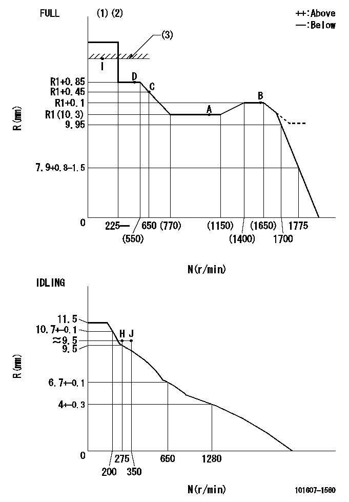
N:Pump speed
R:Rack position (mm)
(1)Torque cam stamping: T1
(2)Tolerance for racks not indicated: +-0.05mm.
(3)RACK LIMIT
----------
T1=F66
----------
----------
T1=F66
----------
Speed control lever angle

F:Full speed
I:Idle
(1)Use the hole at R = aa
(2)Stopper bolt set position 'H'
----------
aa=40mm
----------
a=26deg+-5deg b=37deg+-3deg
----------
aa=40mm
----------
a=26deg+-5deg b=37deg+-3deg
Stop lever angle

N:Engine manufacturer's normal use
S:Stop the pump.
(1)Free (at shipping)
(2)Use the hole at R = aa
(3)Rack position corresponding to bb
(4)Set the stopper bolt so that speed = cc and rack position = dd.
(5)After setting the stopper bolt, confirm non-injection at speed ee. (Rack position = ff or less)
----------
aa=40mm bb=16mm cc=1700r/min dd=6.5-0.5mm ee=275r/min ff=8mm
----------
a=8deg+-5deg b=15deg+-5deg c=25deg+-5deg
----------
aa=40mm bb=16mm cc=1700r/min dd=6.5-0.5mm ee=275r/min ff=8mm
----------
a=8deg+-5deg b=15deg+-5deg c=25deg+-5deg
Timing setting

(1)Pump vertical direction
(2)Position of timer's tooth at No 1 cylinder's beginning of injection
(3)B.T.D.C.: aa
(4)-
----------
aa=12deg
----------
a=(2deg)
----------
aa=12deg
----------
a=(2deg)
Information:
TECHNICAL INFORMATION BULLETIN November 30, 2005
This Technical Information Bulletin replaces the November 11, 2005 TIB "System Malfunctions Related To The Injection Actuation Pressure Sensors In Excavators, Wheel Loaders, Engines, Track-Type Tractors and Track Loaders". Disregard the November 11, 2005 TIB. Refer to the following information.
Excavators 322C (EMR215-523,MAR165-468)
325C (CRB650-1677,CSJ800-1486)
(DTF276-285,JLC283-306)
(JLD313-348)
330C (CAP950-2085,CGZ444-889)
(JCD285-351,MKM308-316)
330CL(JNK238-343)
Wheel Loaders 938GII (PHN550-2023)
950GII (AYB693-1086)
(AYL1039-2384)
962GII (AYE530-695,BAB437-758)
Engines C9 (C9B1-266,CSN1-1070)
(JLW1-279,JSC1-395)
(MTB1-1550,X9X1-258)
Track-Type Tractors D6N LGP (ALR1-715)
(ALY1-1932)
(CCG1-261)
(CCS1-402)
D6N XL (AKM1-1694,ALH1-794)
(CBF1-309,CBJ1-448)
(CBL1-400,CCK1-623)
D6RII (AEM1-117,BPM1-104)
(BRJ1-201,CAD1-257)
(FDT1-362)
D6RII LGP (ACJ1-113)
(ADE1-1016)
(AFD1-98)
(BNC1-433)
(BPP1-502)
(BPZ1-532)
D6RII XL (AAX1-139)
(AGM1-111)
(BMJ1-166)
(BMY1-479)
(BPS1-503)
(BRZ1-537)
D6RII XW (AEP1-711)
(BRE1-501)
(DAE1-192)
D6RIII LGP (WCB1-111,WRG1-157)
D6RIII XW (HDC1-132,MRT1-1)
Track Loader 963C (BBD1-2311)
Component Code 1925SUBJECT: System Malfunctions Related To The Injection Actuation Pressure Sensors In Excavators, Wheel Loaders, Engines, Track-Type Tractors and Track Loaders
PROBLEM:
The Injection Actuation Pressure (IAP) sensors are being replaced on machine applications with C7/3126 engines. Some C9 engine models are also affected. The system event code 164-11 or 164-02 leads the technician to replace the sensor. Many of these sensors are no fault found. The result of these failures is loss of production due to unscheduled downtime.
SOLUTION:
Follow current troubleshooting guidelines for highway trucks to troubleshoot the part causing the failure. This will aid the technician in finding the correct part causing the failure. Report any troubleshooting guidelines errors using the feedback function in the Service Information System (SIS Web).
COPYRIGHT 2005 CATERPILLAR
ALL RIGHTS RESERVED