Information injection-pump assembly
ZEXEL
101607-1541
1016071541
MITSUBISHI
ME076739
me076739

Rating:
Cross reference number
ZEXEL
101607-1541
1016071541
MITSUBISHI
ME076739
me076739
Zexel num
Bosch num
Firm num
Name
101607-1541
ME076739 MITSUBISHI
INJECTION-PUMP ASSEMBLY
6D16 * K
6D16 * K
Calibration Data:
Adjustment conditions
Test oil
1404 Test oil ISO4113 or {SAEJ967d}
1404 Test oil ISO4113 or {SAEJ967d}
Test oil temperature
degC
40
40
45
Nozzle and nozzle holder
105780-8140
Bosch type code
EF8511/9A
Nozzle
105780-0000
Bosch type code
DN12SD12T
Nozzle holder
105780-2080
Bosch type code
EF8511/9
Opening pressure
MPa
17.2
Opening pressure
kgf/cm2
175
Injection pipe
Outer diameter - inner diameter - length (mm) mm 6-2-600
Outer diameter - inner diameter - length (mm) mm 6-2-600
Overflow valve
131424-5520
Overflow valve opening pressure
kPa
255
221
289
Overflow valve opening pressure
kgf/cm2
2.6
2.25
2.95
Tester oil delivery pressure
kPa
157
157
157
Tester oil delivery pressure
kgf/cm2
1.6
1.6
1.6
Direction of rotation (viewed from drive side)
Left L
Left L
Injection timing adjustment
Direction of rotation (viewed from drive side)
Left L
Left L
Injection order
1-5-3-6-
2-4
Pre-stroke
mm
3.2
3.15
3.25
Beginning of injection position
Governor side NO.1
Governor side NO.1
Difference between angles 1
Cal 1-5 deg. 60 59.5 60.5
Cal 1-5 deg. 60 59.5 60.5
Difference between angles 2
Cal 1-3 deg. 120 119.5 120.5
Cal 1-3 deg. 120 119.5 120.5
Difference between angles 3
Cal 1-6 deg. 180 179.5 180.5
Cal 1-6 deg. 180 179.5 180.5
Difference between angles 4
Cyl.1-2 deg. 240 239.5 240.5
Cyl.1-2 deg. 240 239.5 240.5
Difference between angles 5
Cal 1-4 deg. 300 299.5 300.5
Cal 1-4 deg. 300 299.5 300.5
Injection quantity adjustment
Adjusting point
-
Rack position
11.6
Pump speed
r/min
850
850
850
Each cylinder's injection qty
mm3/st.
72.5
70.3
74.7
Basic
*
Fixing the rack
*
Standard for adjustment of the maximum variation between cylinders
*
Injection quantity adjustment_02
Adjusting point
H
Rack position
9.5+-0.5
Pump speed
r/min
275
275
275
Each cylinder's injection qty
mm3/st.
8.3
7.1
9.5
Fixing the rack
*
Standard for adjustment of the maximum variation between cylinders
*
Injection quantity adjustment_03
Adjusting point
A
Rack position
R1(11.6)
Pump speed
r/min
850
850
850
Average injection quantity
mm3/st.
72.5
71.5
73.5
Basic
*
Fixing the lever
*
Injection quantity adjustment_04
Adjusting point
B
Rack position
R1-0.15
Pump speed
r/min
1400
1400
1400
Average injection quantity
mm3/st.
79.5
75.5
83.5
Fixing the lever
*
Injection quantity adjustment_05
Adjusting point
C
Rack position
R1+0.65
Pump speed
r/min
500
500
500
Average injection quantity
mm3/st.
71.5
67.5
75.5
Fixing the lever
*
Injection quantity adjustment_06
Adjusting point
I
Rack position
14.8+-0.
2
Pump speed
r/min
100
100
100
Average injection quantity
mm3/st.
120
100
140
Fixing the lever
*
Rack limit
*
Timer adjustment
Pump speed
r/min
1150
Advance angle
deg.
0.5
Timer adjustment_02
Pump speed
r/min
1200
Advance angle
deg.
0.9
0.4
1.4
Timer adjustment_03
Pump speed
r/min
1380
Advance angle
deg.
5
4.5
5.5
Remarks
Finish
Finish
Test data Ex:
Governor adjustment
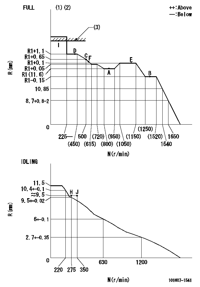
N:Pump speed
R:Rack position (mm)
(1)Torque cam stamping: T1
(2)Tolerance for racks not indicated: +-0.05mm.
(3)RACK LIMIT: RAL
----------
T1=G26 RAL=14.8+-0.2mm
----------
----------
T1=G26 RAL=14.8+-0.2mm
----------
Speed control lever angle

F:Full speed
I:Idle
(1)Stopper bolt set position 'H'
----------
----------
a=20deg+-5deg b=(40deg)+-3deg
----------
----------
a=20deg+-5deg b=(40deg)+-3deg
Stop lever angle

N:Engine manufacturer's normal use
S:Stop the pump.
(1)Set the stopper bolt at pump speed = aa and rack position = bb (non-injection rack position). Confirm non-injection.
(2)After setting the stopper bolt, confirm non-injection at speed cc. Rack position = dd (non-injection rack position).
(3)Rack position = approximately ee.
(4)Free (at shipping)
----------
aa=1400r/min bb=6.9-0.5mm cc=275r/min dd=(8.9)-0.5mm ee=15mm
----------
a=36.5deg+-5deg b=(25deg) c=13.5deg+-5deg
----------
aa=1400r/min bb=6.9-0.5mm cc=275r/min dd=(8.9)-0.5mm ee=15mm
----------
a=36.5deg+-5deg b=(25deg) c=13.5deg+-5deg
0000001501 MICRO SWITCH
Adjustment of the micro-switch
Adjust the bolt to obtain the following lever position when the micro-switch is ON.
(1)Speed N1
(2)Rack position Ra
----------
N1=400r/min Ra=9.2+-0.1mm
----------
----------
N1=400r/min Ra=9.2+-0.1mm
----------
0000001601 LEVER
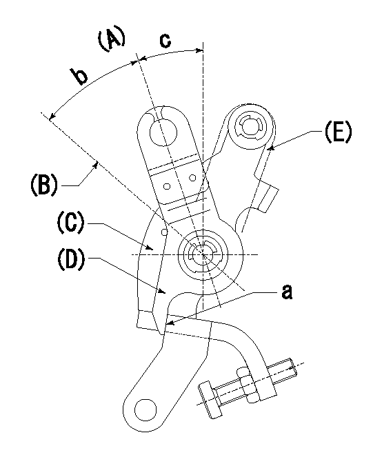
(A) Idle
(B) Full speed
(C) Base lever
(D) Accelerator lever
(E) Accelerator lever delivery position
1. Measure speed lever angle
(1)Measure the angle when the accelerator lever (D) contacted the base lever (C) at a.
----------
----------
b=(40deg)+-3deg c=20deg+-5deg
----------
----------
b=(40deg)+-3deg c=20deg+-5deg
Timing setting

(1)Pump vertical direction
(2)Position of timer's tooth at No 1 cylinder's beginning of injection
(3)B.T.D.C.: aa
(4)-
----------
aa=11deg
----------
a=(1deg)
----------
aa=11deg
----------
a=(1deg)
Information:
TECHNICAL INFORMATION BULLETIN July 7, 2004
Engines
Machines 3054E (304, CRX)
3056E (356, CPT)
315C (ANF)
320C (CCD)
924G (DDA, DFZ, RBB, WGX, WMB)
928G (DJD, WLG)
AP-655C (CDG)
CP-563E (BWE, CNT)
CP-573E (ASY)
CS-563E (ASA, CNG)
CS-583E (DAJ)
CS-663E (DAG)
IT28G (DBT, EWF, WAC)
M313C (BDR)
M315C (BDM)
M316C (BDX)
M318C (BCZ)
M322C (BDK)
TH330B (SLB)
Component Code 1251SUBJECT: Replace Failed 3054E and 3056E Fuel Injection Pumps with New Pumps from Cat Parts
PROBLEM:
The 3054E and 3056E engines use electronic Bosch fuel injection pumps. These are new engine applications for these pumps. Therefore, initially, Bosch is requesting that all failed pumps are to be replaced by new pumps from Cat Parts. Replaced pumps are to be returned to Bosch through Peoria, IL or Peterborough, U.K. as described below, depending on location.
SOLUTION:
Failed fuel injection pumps are to be replaced by new pumps out of Cat Parts. Pumps should only be replaced after a full diagnostic check of the Engine and Machine. Troubleshooting Guide, RENR2417, should be used in order to perform the full diagnostic check. Replaced pumps must be returned to Caterpillar Inc. for forwarding to the supplier for full failure analysis.
Pumps from NACD and LACD territories are to be packaged and shipped to:
Caterpillar Service Claims Room
8201 N. University
Peoria, IL 61615 USA
Attn: 3000 Series Engine Service Engineer
Pumps from EAME and APD territories are to be packaged and shipped to:
Perkins Engines Ltd.
Return Parts Centre-C/O Ron Chandler
Peterborough PE1 5NA
U.K.
All failure information is to be submitted with each pump. Dealers are requested to supply FULL details regarding their investigations into the failure of the pump. This information will allow for a more detailed analysis of the pump failure. Attach the normal service claim form. The following list represents the minimum amount of additional information that should be submitted with the faulty pump and the service claim form.
A breakdown of the fault finding process employed using RENR2417
Details of the failure including symptoms that were experienced (Hard to start, etc?)
Screen prints from Caterpillar Electronic Technician (Cat ET) describing both the logged and active fault codes at the time of investigation
Other relevant details from customers include engine and machine history and the usage at the time of the incident
Dealers from EAME should email the above information to Alex Radjenovic at Radjenovic_Alex@perkins.com
Dealers from NACD and LACD should email the above information to Robert Stoetzer at Stoetzer_Robert_A
All returned fuel injection pump ports must be sealed prior to shipment to prevent contamination. The protective caps used on the new pump ports MUST be transferred to the failed pump ports prior to return shipment to avoid contamination in route to the supplier. Also, it is imperative that the pump be protected against damage during transit. Damage during transit may prevent assessment by the supplier.
Dealers in the NACD territory are to follow the established parts return procedures per Service Warranty Bulletin No. 7.1.
Dealers outside of the NACD territory are required to pay for the shipping cost of the returned pump, then claim the shipping cost as a miscellaneous expense on the warranty claim.
COPYRIGHT 2004 CATERPILLAR
ALL RIGHTS RESERVED
Have questions with 101607-1541?
Group cross 101607-1541 ZEXEL
Mitsubishi
Mitsubishi
Mitsubishi
Mitsubishi
101607-1541
ME076739
INJECTION-PUMP ASSEMBLY
6D16
6D16