Information injection-pump assembly
ZEXEL
101607-1540
1016071540
Rating:
Cross reference number
ZEXEL
101607-1540
1016071540
Zexel num
Bosch num
Firm num
Name
101607-1540
INJECTION-PUMP ASSEMBLY
Calibration Data:
Adjustment conditions
Test oil
1404 Test oil ISO4113 or {SAEJ967d}
1404 Test oil ISO4113 or {SAEJ967d}
Test oil temperature
degC
40
40
45
Nozzle and nozzle holder
105780-8140
Bosch type code
EF8511/9A
Nozzle
105780-0000
Bosch type code
DN12SD12T
Nozzle holder
105780-2080
Bosch type code
EF8511/9
Opening pressure
MPa
17.2
Opening pressure
kgf/cm2
175
Injection pipe
Outer diameter - inner diameter - length (mm) mm 6-2-600
Outer diameter - inner diameter - length (mm) mm 6-2-600
Overflow valve
131424-5520
Overflow valve opening pressure
kPa
255
221
289
Overflow valve opening pressure
kgf/cm2
2.6
2.25
2.95
Tester oil delivery pressure
kPa
157
157
157
Tester oil delivery pressure
kgf/cm2
1.6
1.6
1.6
Direction of rotation (viewed from drive side)
Left L
Left L
Injection timing adjustment
Direction of rotation (viewed from drive side)
Left L
Left L
Injection order
1-5-3-6-
2-4
Pre-stroke
mm
3.2
3.15
3.25
Beginning of injection position
Governor side NO.1
Governor side NO.1
Difference between angles 1
Cal 1-5 deg. 60 59.5 60.5
Cal 1-5 deg. 60 59.5 60.5
Difference between angles 2
Cal 1-3 deg. 120 119.5 120.5
Cal 1-3 deg. 120 119.5 120.5
Difference between angles 3
Cal 1-6 deg. 180 179.5 180.5
Cal 1-6 deg. 180 179.5 180.5
Difference between angles 4
Cyl.1-2 deg. 240 239.5 240.5
Cyl.1-2 deg. 240 239.5 240.5
Difference between angles 5
Cal 1-4 deg. 300 299.5 300.5
Cal 1-4 deg. 300 299.5 300.5
Injection quantity adjustment
Adjusting point
-
Rack position
11.6
Pump speed
r/min
850
850
850
Each cylinder's injection qty
mm3/st.
72.5
70.3
74.7
Basic
*
Fixing the rack
*
Standard for adjustment of the maximum variation between cylinders
*
Injection quantity adjustment_02
Adjusting point
H
Rack position
9.5+-0.5
Pump speed
r/min
275
275
275
Each cylinder's injection qty
mm3/st.
8.3
7.1
9.5
Fixing the rack
*
Standard for adjustment of the maximum variation between cylinders
*
Injection quantity adjustment_03
Adjusting point
A
Rack position
R1(11.6)
Pump speed
r/min
850
850
850
Average injection quantity
mm3/st.
72.5
71.5
73.5
Basic
*
Fixing the lever
*
Injection quantity adjustment_04
Adjusting point
B
Rack position
R1-0.15
Pump speed
r/min
1400
1400
1400
Average injection quantity
mm3/st.
79.5
75.5
83.5
Fixing the lever
*
Injection quantity adjustment_05
Adjusting point
C
Rack position
R1+0.65
Pump speed
r/min
500
500
500
Average injection quantity
mm3/st.
71.5
67.5
75.5
Fixing the lever
*
Injection quantity adjustment_06
Adjusting point
I
Rack position
14.8+-0.
2
Pump speed
r/min
100
100
100
Average injection quantity
mm3/st.
120
100
140
Fixing the lever
*
Rack limit
*
Timer adjustment
Pump speed
r/min
1150
Advance angle
deg.
0.5
Timer adjustment_02
Pump speed
r/min
1200
Advance angle
deg.
0.9
0.4
1.4
Timer adjustment_03
Pump speed
r/min
1380
Advance angle
deg.
5
4.5
5.5
Remarks
Finish
Finish
Test data Ex:
Governor adjustment
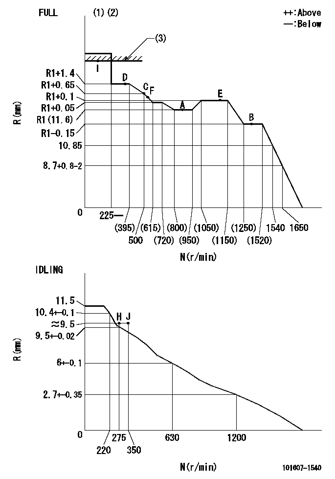
N:Pump speed
R:Rack position (mm)
(1)Torque cam stamping: T1
(2)Tolerance for racks not indicated: +-0.05mm.
(3)RACK LIMIT: RAL
----------
T1=F14 RAL=14.8+-0.2mm
----------
----------
T1=F14 RAL=14.8+-0.2mm
----------
Speed control lever angle

F:Full speed
I:Idle
(1)Stopper bolt set position 'H'
----------
----------
a=20deg+-5deg b=(40deg)+-3deg
----------
----------
a=20deg+-5deg b=(40deg)+-3deg
Stop lever angle

N:Engine manufacturer's normal use
S:Stop the pump.
(1)Pump speed = aa and rack position = bb (non-injection rack position)
(2)Set the stopper bolt (confirm non-injection).
(3)Corresponding to rack position = cc.
(4)Free (at shipping)
----------
aa=1400r/min bb=6.9-0.5mm cc=15mm
----------
a=36.5deg+-5deg b=(25deg) c=13.5deg+-5deg
----------
aa=1400r/min bb=6.9-0.5mm cc=15mm
----------
a=36.5deg+-5deg b=(25deg) c=13.5deg+-5deg
0000001501 MICRO SWITCH
Adjustment of the micro-switch
Adjust the bolt to obtain the following lever position when the micro-switch is ON.
(1)Speed N1
(2)Rack position Ra
----------
N1=400r/min Ra=9.2+-0.1mm
----------
----------
N1=400r/min Ra=9.2+-0.1mm
----------
0000001601 LEVER
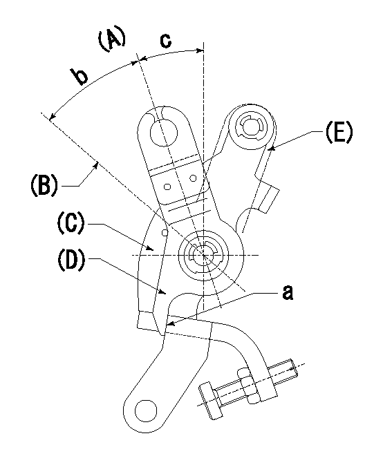
(A) Idle
(B) Full speed
(C) Base lever
(D) Accelerator lever
(E) Accelerator lever delivery position
1. Measure speed lever angle
(1)Measure the angle when the accelerator lever (D) contacted the base lever (C) at a.
----------
----------
b=(40deg)+-3deg c=20deg+-5deg
----------
----------
b=(40deg)+-3deg c=20deg+-5deg
Timing setting

(1)Pump vertical direction
(2)Position of timer's tooth at No 1 cylinder's beginning of injection
(3)B.T.D.C.: aa
(4)-
----------
aa=11deg
----------
a=(1deg)
----------
aa=11deg
----------
a=(1deg)
Information:
CONFIDENTIAL
TECHNICAL INFORMATION BULLETIN March 27, 2002
Engines 3516 (25Z, 5SJ, 7KM, CMD, 4XF)
3516B (1HZ, 7RN, 5AN, FDN, BDP,
6HN)
Component Code: 1404SUBJECT: Generator Stator Adapter Cracking on 3516 Diesel Generator Set
PROBLEM:
Certain SR4B single bearing generators may develop cracks in the adapter assembly. The generator adapter is the welded assembly, part of the generator stator, consisting of the front adapter ring that bolts to the flywheel housing and the individual support bars welded to this adapter ring. Several different weld failure modes exist for the generator adapter. First, there may be cracks along the top weld leg between the adapter supports and the front adapter ring. Second, there may be cracks at the toe of the welds joining the adapter support bars to the front ring. These cracks appear in the heat-affected zone of the welds and propagate into the front adapter ring of the generator. The third failure mode is radial cracks between the end ring of the generator adapter and the stator housing. This type of crack most likely occurs after the support welds have failed. After the support welds have failed, the cracks at the toe of the support bars propagate into the ring and create a stress riser.
SOLUTION:
Caterpillar is redesigning the current product and is also working on a solution that will address the existing units in the field. At this time, it is NOT recommended to immediately replace cracked generator stators, nor is it recommended to re-weld the cracked adapters as a field repair. Rather, a crack observation and evaluation process should be established for each individual case. It is anticipated that the first recognizable cracks on suspect generators (cracks size of 0.25" and larger) may appear as early as 300 hours. If any of the above-described cracks are found, the servicing dealer should contact Caterpillar Service. The servicing dealer should also assist in periodic inspection of the cracks in an effort to determine the next action.
Contact (if different from sender): Miro Halicek (770) 233-5877 or Marc Sylvester (770) 233-5630.
COPYRIGHT 2002 CATERPILLAR
ALL RIGHTS RESERVED
Have questions with 101607-1540?
Group cross 101607-1540 ZEXEL
Mitsubishi
Mitsubishi
Mitsubishi
101607-1540
INJECTION-PUMP ASSEMBLY