Information injection-pump assembly
ZEXEL
101607-1450
1016071450

Rating:
Service parts 101607-1450 INJECTION-PUMP ASSEMBLY:
1.
_
6.
COUPLING PLATE
7.
COUPLING PLATE
8.
_
9.
_
11.
Nozzle and Holder
ME076000
12.
Open Pre:MPa(Kqf/cm2)
21.6{220}

15.
NOZZLE SET
Cross reference number
ZEXEL
101607-1450
1016071450
Zexel num
Bosch num
Firm num
Name
101607-1450
INJECTION-PUMP ASSEMBLY
Calibration Data:
Adjustment conditions
Test oil
1404 Test oil ISO4113 or {SAEJ967d}
1404 Test oil ISO4113 or {SAEJ967d}
Test oil temperature
degC
40
40
45
Nozzle and nozzle holder
105780-8140
Bosch type code
EF8511/9A
Nozzle
105780-0000
Bosch type code
DN12SD12T
Nozzle holder
105780-2080
Bosch type code
EF8511/9
Opening pressure
MPa
17.2
Opening pressure
kgf/cm2
175
Injection pipe
Outer diameter - inner diameter - length (mm) mm 6-2-600
Outer diameter - inner diameter - length (mm) mm 6-2-600
Overflow valve
131424-5520
Overflow valve opening pressure
kPa
255
221
289
Overflow valve opening pressure
kgf/cm2
2.6
2.25
2.95
Tester oil delivery pressure
kPa
157
157
157
Tester oil delivery pressure
kgf/cm2
1.6
1.6
1.6
Direction of rotation (viewed from drive side)
Left L
Left L
Injection timing adjustment
Direction of rotation (viewed from drive side)
Left L
Left L
Injection order
1-5-3-6-
2-4
Pre-stroke
mm
3.3
3.25
3.35
Beginning of injection position
Governor side NO.1
Governor side NO.1
Difference between angles 1
Cal 1-5 deg. 60 59.5 60.5
Cal 1-5 deg. 60 59.5 60.5
Difference between angles 2
Cal 1-3 deg. 120 119.5 120.5
Cal 1-3 deg. 120 119.5 120.5
Difference between angles 3
Cal 1-6 deg. 180 179.5 180.5
Cal 1-6 deg. 180 179.5 180.5
Difference between angles 4
Cyl.1-2 deg. 240 239.5 240.5
Cyl.1-2 deg. 240 239.5 240.5
Difference between angles 5
Cal 1-4 deg. 300 299.5 300.5
Cal 1-4 deg. 300 299.5 300.5
Injection quantity adjustment
Adjusting point
-
Rack position
11.1
Pump speed
r/min
850
850
850
Each cylinder's injection qty
mm3/st.
63.7
61.8
65.6
Basic
*
Fixing the rack
*
Standard for adjustment of the maximum variation between cylinders
*
Injection quantity adjustment_02
Adjusting point
D
Rack position
8.7+-0.5
Pump speed
r/min
500
500
500
Each cylinder's injection qty
mm3/st.
10.2
8.7
11.7
Fixing the rack
*
Standard for adjustment of the maximum variation between cylinders
*
Injection quantity adjustment_03
Adjusting point
A
Rack position
R1(11.1)
Pump speed
r/min
850
850
850
Average injection quantity
mm3/st.
63.7
62.7
64.7
Basic
*
Fixing the lever
*
Injection quantity adjustment_04
Adjusting point
C
Rack position
R1+0.2
Pump speed
r/min
500
500
500
Average injection quantity
mm3/st.
41.7
37.7
45.7
Fixing the lever
*
Injection quantity adjustment_05
Adjusting point
I
Rack position
-
Pump speed
r/min
100
100
100
Average injection quantity
mm3/st.
73
63
83
Fixing the lever
*
Rack limit
*
Injection quantity adjustment_06
Adjusting point
H
Rack position
9.5+-0.5
Pump speed
r/min
275
275
275
Each cylinder's injection qty
mm3/st.
10
8.5
11.5
Fixing the rack
*
Remarks
(check)
(check)
Timer adjustment
Pump speed
r/min
900--
Advance angle
deg.
0
0
0
Remarks
Start
Start
Timer adjustment_02
Pump speed
r/min
850
Advance angle
deg.
0.5
Timer adjustment_03
Pump speed
r/min
1200
Advance angle
deg.
2.7
2.2
3.2
Timer adjustment_04
Pump speed
r/min
1500
Advance angle
deg.
5
4.5
5.5
Remarks
Finish
Finish
Test data Ex:
Governor adjustment

N:Pump speed
R:Rack position (mm)
(1)Torque cam stamping: T1
(2)Tolerance for racks not indicated: +-0.05mm.
(3)RACK LIMIT
----------
T1=F35
----------
----------
T1=F35
----------
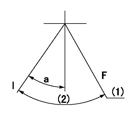
Speed control lever angle

F:Full speed
I:Idle
(1)Use the hole at R = aa
(2)Stopper bolt set position 'H'
----------
aa=29mm
----------
a=10deg+-5deg b=(46deg)+-3deg
----------
aa=29mm
----------
a=10deg+-5deg b=(46deg)+-3deg
Stop lever angle
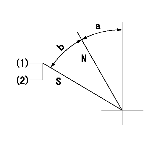
N:Pump normal
S:Stop the pump.
(1)Set the stopper bolt at pump speed = aa and rack position = bb (non-injection rack position). Confirm non-injection.
(2)After setting the stopper bolt, confirm non-injection at speed cc. Rack position = dd (non-injection rack position).
----------
aa=1480r/min bb=6.7-0.5mm cc=275r/min dd=(8.3)-0.5mm
----------
a=11.5deg+-5deg b=(27deg)+-5deg
----------
aa=1480r/min bb=6.7-0.5mm cc=275r/min dd=(8.3)-0.5mm
----------
a=11.5deg+-5deg b=(27deg)+-5deg
0000001201
F:At operation, hold it in the full speed position.
I:Idle
(1)At rack position aa and pump speed bb, set the stopper bolt. (After setting it, apply red paint.)
(2)Actual measurement
----------
aa=7.6mm bb=1530r/min
----------
a=15deg+-5deg
----------
aa=7.6mm bb=1530r/min
----------
a=15deg+-5deg
0000001501 MICRO SWITCH
Adjustment of the micro-switch
Adjust the bolt to obtain the following lever position when the micro-switch is ON.
(1)Speed N1
(2)Rack position Ra
----------
N1=400r/min Ra=9.2+-0.1mm
----------
----------
N1=400r/min Ra=9.2+-0.1mm
----------
Timing setting

(1)Pump vertical direction
(2)Position of timer's tooth at No 1 cylinder's beginning of injection
(3)B.T.D.C.: aa
(4)-
----------
aa=14deg
----------
a=(0deg)
----------
aa=14deg
----------
a=(0deg)
Information:
27Jun2018
(Revised 10Jul2018)
U-356
A-265
D-311
O-319
Parts stock action only
PRODUCT IMPROVEMENT PROGRAM FOR INSPECTING AND REPLACING INTAKE VALVES IN CERTAIN GAS AND DIESEL 3600 REMAN CYLINDER HEADS
7750 PI70709
Caterpillar’s obligations under this Service Letter are subject to, and shall not apply in contravention of, the laws, rules, regulations, directives, ordinances, orders, or statutes of the United States, or of any other applicable jurisdiction, without recourse or liability with respect to Caterpillar.
When submitting claim for Parts Stock Action, Use the appropriate 99Z as the s/n, the appropriate Service Letter Program Number as the Part number in the Part Causing Failure field, "7751" as the Group Number, "56" as the Description Code.
The information supplied in this service letter may not be valid after the termination date of this program.Do not perform the work outlined in this Service Letter after the termination date without first contacting your Caterpillar product analyst.
This Revised Service Letter replaces the 27Jun2018 Service Letter. Changes have been made to the Action Required.
TERMINATION DATE
30Sep2018
PROBLEM
The existing remanufactured intake valves installed in certain Reman 3600 cylinder heads may have improper surface finish, which may lead to excessive bridge wear. If the affected valves cause excessive early bridge wear, the intake valves may drop.
ACTION REQUIRED
Please inspect all dealer stock of the following Reman part numbers: 10R-1835, 20R-6518, 10R-9360, 10R-1602, 10R-1496, 0R-7467, 10R-3484, 10R-4829, and 10R-3474.
Inspection procedure:
1) Check the packaging label date code on the Reman cylinder head. If the packaging label date code is dated on or after D08M06Y18 (8-June-2018), return the head to dealer stock without further action.
2) If the packaging label date code is dated earlier than 8-June-2018, remove the head from the box. Inspect the intake valves for part number (if the valve is remanufactured the part number will be hand-scribed, pin stamped, or both on the bottom of the valve head). If a hand-scribed Reman part number is present, remove this valve and replace with new. Reuse all rotocoils, keepers, springs, and seals. Replace all valves that have hand-scribed part numbers even if a pin stamp part number is also present. Refer to Image 1 for an example of both hand-scribed and pin stamped part numbers. Refer to Image 2 for a table of intake valves required for a given cylinder head part number.
If a valve without a hand-scribed Reman part number is present (or without a part number at all), return the head to the crate and ensure rust preventative is applied to any area it may have been removed from. Return the head to dealer stock.
Image1
Image2
SERVICE CLAIM ALLOWANCES
This letter allows 0.5 hours of labor for the inspection of each Reman 3600 cylinder head with a packaging date code prior to 8-June-2018. An additional 2.5 hours, 3 hours total, is allowed for every cylinder head that requires an intake valve(s) replacement.One valve will allowed for each valve that requires replacement up to two per head. See the chart in Image 2 for the applicable part numbers.
PARTS DISPOSITION
Handle the parts in accordance with your Warranty Bulletin on warranty parts handling.
Have questions with 101607-1450?
Group cross 101607-1450 ZEXEL
Mitsubishi
101607-1450
INJECTION-PUMP ASSEMBLY