Information injection-pump assembly
BOSCH
F 01G 09U 05A
f01g09u05a
ZEXEL
101607-1420
1016071420
MITSUBISHI
ME076682
me076682

Rating:
Include in #1:
101401-7560
as _
Cross reference number
BOSCH
F 01G 09U 05A
f01g09u05a
ZEXEL
101607-1420
1016071420
MITSUBISHI
ME076682
me076682
Zexel num
Bosch num
Firm num
Name
101607-1420
F 01G 09U 05A
ME076682 MITSUBISHI
INJECTION-PUMP ASSEMBLY
6D14 * K
6D14 * K
Calibration Data:
Adjustment conditions
Test oil
1404 Test oil ISO4113 or {SAEJ967d}
1404 Test oil ISO4113 or {SAEJ967d}
Test oil temperature
degC
40
40
45
Nozzle and nozzle holder
105780-8140
Bosch type code
EF8511/9A
Nozzle
105780-0000
Bosch type code
DN12SD12T
Nozzle holder
105780-2080
Bosch type code
EF8511/9
Opening pressure
MPa
17.2
Opening pressure
kgf/cm2
175
Injection pipe
Outer diameter - inner diameter - length (mm) mm 6-2-600
Outer diameter - inner diameter - length (mm) mm 6-2-600
Overflow valve
131424-5520
Overflow valve opening pressure
kPa
255
221
289
Overflow valve opening pressure
kgf/cm2
2.6
2.25
2.95
Tester oil delivery pressure
kPa
157
157
157
Tester oil delivery pressure
kgf/cm2
1.6
1.6
1.6
Direction of rotation (viewed from drive side)
Left L
Left L
Injection timing adjustment
Direction of rotation (viewed from drive side)
Left L
Left L
Injection order
1-5-3-6-
2-4
Pre-stroke
mm
3.3
3.25
3.35
Beginning of injection position
Governor side NO.1
Governor side NO.1
Difference between angles 1
Cal 1-5 deg. 60 59.5 60.5
Cal 1-5 deg. 60 59.5 60.5
Difference between angles 2
Cal 1-3 deg. 120 119.5 120.5
Cal 1-3 deg. 120 119.5 120.5
Difference between angles 3
Cal 1-6 deg. 180 179.5 180.5
Cal 1-6 deg. 180 179.5 180.5
Difference between angles 4
Cyl.1-2 deg. 240 239.5 240.5
Cyl.1-2 deg. 240 239.5 240.5
Difference between angles 5
Cal 1-4 deg. 300 299.5 300.5
Cal 1-4 deg. 300 299.5 300.5
Injection quantity adjustment
Adjusting point
-
Rack position
10.6
Pump speed
r/min
850
850
850
Each cylinder's injection qty
mm3/st.
61
59.2
62.8
Basic
*
Fixing the rack
*
Standard for adjustment of the maximum variation between cylinders
*
Injection quantity adjustment_02
Adjusting point
H
Rack position
9.5+-0.5
Pump speed
r/min
275
275
275
Each cylinder's injection qty
mm3/st.
10.5
9
12
Fixing the rack
*
Standard for adjustment of the maximum variation between cylinders
*
Injection quantity adjustment_03
Adjusting point
A
Rack position
R1(10.6)
Pump speed
r/min
850
850
850
Average injection quantity
mm3/st.
61
60
62
Basic
*
Fixing the lever
*
Injection quantity adjustment_04
Adjusting point
D
Rack position
R1+0.6
Pump speed
r/min
600
600
600
Average injection quantity
mm3/st.
62
58
66
Fixing the lever
*
Injection quantity adjustment_05
Adjusting point
I
Rack position
14.1+-0.
5
Pump speed
r/min
100
100
100
Average injection quantity
mm3/st.
90
70
110
Fixing the lever
*
Rack limit
*
Timer adjustment
Pump speed
r/min
900--
Advance angle
deg.
0
0
0
Remarks
Start
Start
Timer adjustment_02
Pump speed
r/min
850
Advance angle
deg.
0.5
Timer adjustment_03
Pump speed
r/min
900
Advance angle
deg.
0.8
Timer adjustment_04
Pump speed
r/min
1200
Advance angle
deg.
2.6
2.1
3.1
Timer adjustment_05
Pump speed
r/min
1500
Advance angle
deg.
5.5
5
6
Remarks
Finish
Finish
Test data Ex:
Governor adjustment
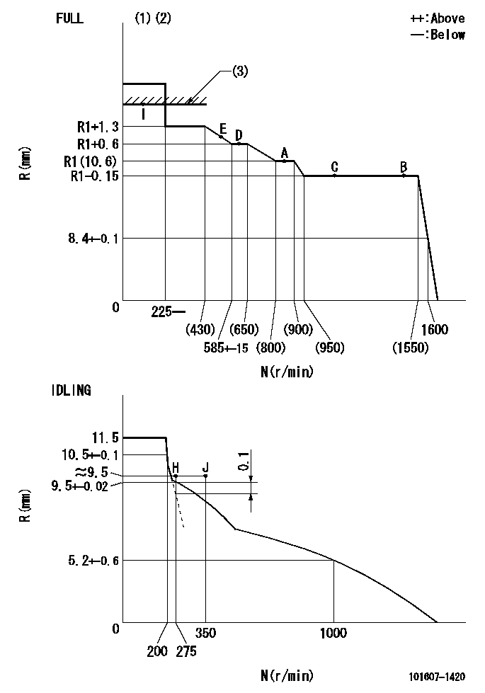
N:Pump speed
R:Rack position (mm)
(1)Torque cam stamping: T1
(2)Tolerance for racks not indicated: +-0.05mm.
(3)RACK LIMIT
----------
T1=D89
----------
----------
T1=D89
----------
Speed control lever angle

F:Full speed
I:Idle
(1)Stopper bolt set position 'H'
----------
----------
a=24deg+-5deg b=42deg+-3deg
----------
----------
a=24deg+-5deg b=42deg+-3deg
Stop lever angle

N:Engine manufacturer's normal use
S:Stop the pump.
(1)Set the stopper bolt at pump speed = aa and rack position = bb (non-injection rack position). Confirm non-injection.
(2)After setting the stopper bolt, confirm non-injection at speed cc. Rack position = dd (non-injection rack position).
(3)Rack position = approximately ee.
(4)Free (at shipping)
----------
aa=1550r/min bb=7.2-0.5mm cc=275r/min dd=8.2mm ee=17.4mm
----------
a=38.5deg+-5deg b=(27deg) c=17deg+-5deg
----------
aa=1550r/min bb=7.2-0.5mm cc=275r/min dd=8.2mm ee=17.4mm
----------
a=38.5deg+-5deg b=(27deg) c=17deg+-5deg
0000001501 MICRO SWITCH
Adjustment of the micro-switch
Adjust the bolt to obtain the following lever position when the micro-switch is ON.
(1)Speed N1
(2)Rack position Ra
----------
N1=400r/min Ra=9.2+-0.1mm
----------
----------
N1=400r/min Ra=9.2+-0.1mm
----------
0000001601 LEVER
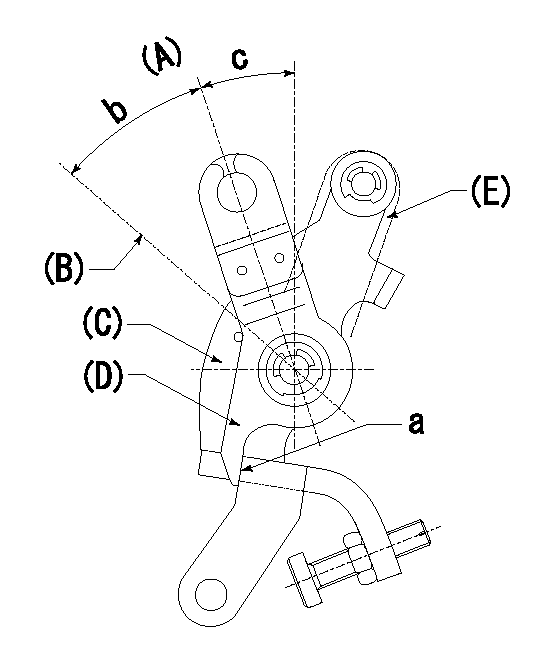
(A) Idle
(B) Full speed
(C) Base lever
(D) Accelerator lever
(E) Accelerator lever delivery position
1. Measure speed lever angle
(1)Measure the angle when the accelerator lever (D) contacted the base lever (C) at a.
----------
----------
b=42deg+-3deg c=24deg+-5deg
----------
----------
b=42deg+-3deg c=24deg+-5deg
Timing setting

(1)Pump vertical direction
(2)Position of timer's tooth at No 1 cylinder's beginning of injection
(3)B.T.D.C.: aa
(4)-
----------
aa=16deg
----------
a=(1deg)
----------
aa=16deg
----------
a=(1deg)
Information:
*******Group 16*******
100% 100% 0% 0% 0% 0%
This is a 5.0-hour job for Group 16
Caterpillar Dealer Suggested Customer Suggested
Parts % Labor Hrs% Parts % Labor Hrs% Parts % Labor Hrs%
*******Group 17*******
100% 100% 0% 0% 0% 0%
This is a 7.0-hour job for Group 17
Caterpillar Dealer Suggested Customer Suggested
Parts % Labor Hrs% Parts % Labor Hrs% Parts % Labor Hrs%
*******Group 18*******
100% 100% 0% 0% 0% 0%
This is a 8.0-hour job for Group 18
Caterpillar Dealer Suggested Customer Suggested
Parts % Labor Hrs% Parts % Labor Hrs% Parts % Labor Hrs%
*******Group 19*******
100% 100% 0% 0% 0% 0%
This is a 1.0-hour job for Group 19
PARTS DISPOSITION
Handle the parts in accordance with your Warranty Bulletin on warranty parts handling.
MAKE EVERY EFFORT TO COMPLETE THIS PROGRAM AS SOON AS POSSIBLE.
EXAMPLE COPY OF OWNER NOTIFICATION
XYZ Corporation
3240 Arrow Drive
Anywhere, YZ 99999
PRIORITY - PRODUCT IMPROVEMENT PROGRAM FOR REPLACING FUEL INJECTORS
MODELS INVOLVED - CERTAIN 3508C, 3512B, 3512C, 3516C, AND 3516E GENERATOR SETS, MARINE ENGINES, AND PETROLEUM ENGINES
Dear Cat Product Owner:
Certain fuel injectors need to be replaced on the products listed below. The existing fuel injectors can cause the cylinder to be over fueled and possibly lead to engine damage. You will not be charged for the service performed.
Contact your local Cat dealer immediately to schedule this service. The dealer will advise you of the time required to complete this service.
If you are no longer the owner of this product(s), please contact your local Cat dealer so that our records can be updated. Please refer the dealer to their Service Letter dated 19Mar2018 when scheduling this service.
We regret the inconvenience this may cause you, and urge you to have this service performed as soon as possible to prevent unscheduled downtime.
Caterpillar Inc.
Identification #(s)
Attached to 19Mar2018 Service Letter
Have questions with 101607-1420?
Group cross 101607-1420 ZEXEL
Mitsubishi
101607-1420
F 01G 09U 05A
ME076682
INJECTION-PUMP ASSEMBLY
6D14
6D14